MAX PRO-SERIES RS-232 COMMAND SPECIFICATIONS
1. OVERVIEW
The Panamax
The purpose of this document is to outline the command set used to communicate with the
Commands and responses are in the form of ASCII character STRINGS TERMINATED with ASCII 13, line feed (ASCII 10) or NULL (ASCIØ).
2. CONTROLLER COMMANDS
The following are commands made by the controller to
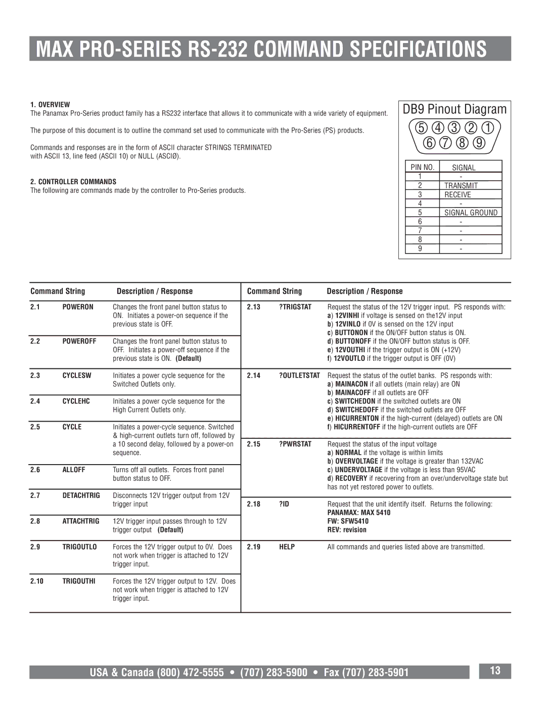
DB9 Pinout Diagram | ||||
5 | 4 | 3 | 2 | 1 |
6 | 7 |
| 8 | 9 |
PIN NO. |
| SIGNAL |
| |
1 |
|
| - |
|
2 | TRANSMIT | |||
3 | RECEIVE |
| ||
4 |
|
| - |
|
5 | SIGNAL GROUND | |||
6 |
|
| - |
|
7 |
|
| - |
|
8 |
|
| - |
|
9 |
|
| - |
|
| Command String | Description / Response | Command String | Description / Response | |||
|
|
|
|
|
|
|
|
2.1 | POWERON | Changes the front panel button status to | 2.13 | ?TRIGSTAT | Request the status of the 12V trigger input. PS responds with: | ||
|
|
| ON. Initiates a |
|
| a) 12VINHI if voltage is sensed on the12V input | |
|
|
| previous state is OFF. |
|
| b) 12VINLO if 0V is sensed on the 12V input | |
|
|
|
|
|
|
| c) BUTTONON if the ON/OFF button status is ON. |
2.2 | POWEROFF | Changes the front panel button status to |
|
| d) BUTTONOFF if the ON/OFF button status is OFF. | ||
|
|
| OFF. Initiates a |
|
| e) 12VOUTHI if the trigger output is ON (+12V) | |
|
|
| previous state is ON. (Default) |
|
| f) 12VOUTLO if the trigger output is OFF (0V) | |
|
|
|
|
|
|
|
|
2.3 | CYCLESW | Initiates a power cycle sequence for the | 2.14 | ?OUTLETSTAT | Request the status of the outlet banks. PS responds with: | ||
|
|
| Switched Outlets only. |
|
| a) MAINACON if all outlets (main relay) are ON | |
|
|
|
|
|
|
| b) MAINACOFF if all outlets are OFF |
2.4 | CYCLEHC | Initiates a power cycle sequence for the |
|
| c) SWITCHEDON if the switched outlets are ON | ||
|
|
| High Current Outlets only. |
|
| d) SWITCHEDOFF if the switched outlets are OFF | |
|
|
|
|
|
|
| e) HICURRENTON if the |
2.5 | CYCLE | Initiates a |
|
| f) HICURRENTOFF if the | ||
|
|
| & |
|
|
|
|
|
|
| a 10 second delay, followed by a | 2.15 | ?PWRSTAT | Request the status of the input voltage | |
|
|
| sequence. |
|
| a) NORMAL if the voltage is within limits | |
|
|
|
|
|
|
| b) OVERVOLTAGE if the voltage is greater than 132VAC |
2.6 | ALLOFF | Turns off all outlets. Forces front panel |
|
| c) UNDERVOLTAGE if the voltage is less than 95VAC | ||
|
|
| button status to OFF. |
|
| d) RECOVERY if recovering from an over/undervoltage state but | |
|
|
|
|
|
|
| has not yet restored power to outlets. |
2.7DETACHTRIG Disconnects 12V trigger output from 12V
|
| trigger input | 2.18 | ?ID | Request that the unit identify itself. Returns the following: |
|
|
|
|
| PANAMAX: MAX 5410 |
2.8 | ATTACHTRIG | 12V trigger input passes through to 12V |
|
| FW: SFW5410 |
|
| trigger output (Default) |
|
| REV: revision |
|
|
|
|
|
|
2.9 | TRIGOUTLO | Forces the 12V trigger output to 0V. Does | 2.19 | HELP | All commands and queries listed above are transmitted. |
|
| not work when trigger is attached to 12V |
|
|
|
|
| trigger input. |
|
|
|
2.10TRIGOUTHI Forces the 12V trigger output to 12V. Does not work when trigger is attached to 12V trigger input.
|
| 13 |
USA & Canada (800) |
|