Controls and Their Functions
s
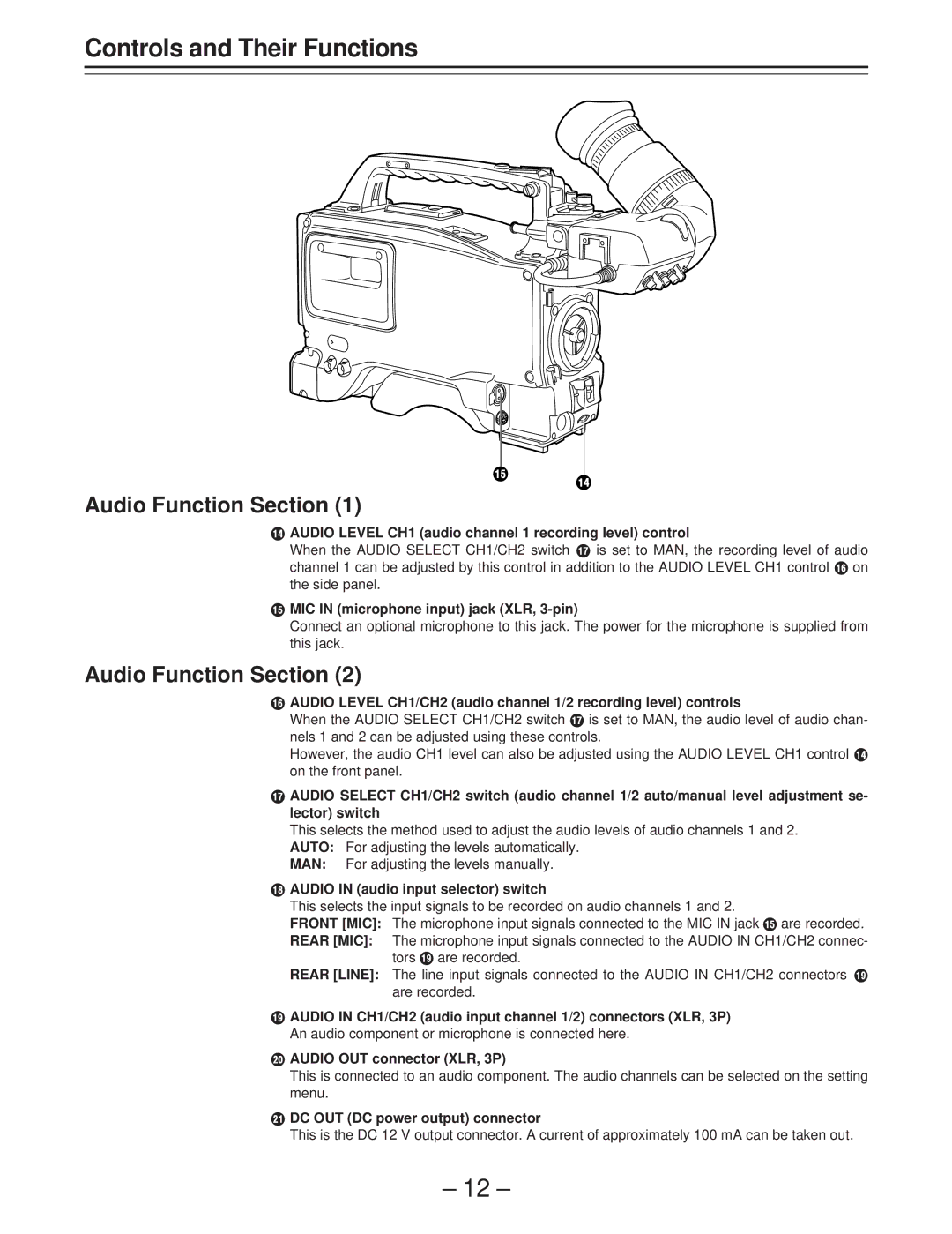
Audio Function Section (1)
r
rAUDIO LEVEL CH1 (audio channel 1 recording level) control
When the AUDIO SELECT CH1/CH2 switch u is set to MAN, the recording level of audio channel 1 can be adjusted by this control in addition to the AUDIO LEVEL CH1 control t on the side panel.
sMIC IN (microphone input) jack (XLR, 3-pin)
Connect an optional microphone to this jack. The power for the microphone is supplied from this jack.
Audio Function Section (2)
tAUDIO LEVEL CH1/CH2 (audio channel 1/2 recording level) controls
When the AUDIO SELECT CH1/CH2 switch u is set to MAN, the audio level of audio chan- nels 1 and 2 can be adjusted using these controls.
However, the audio CH1 level can also be adjusted using the AUDIO LEVEL CH1 control r on the front panel.
uAUDIO SELECT CH1/CH2 switch (audio channel 1/2 auto/manual level adjustment se- lector) switch
This selects the method used to adjust the audio levels of audio channels 1 and 2. AUTO: For adjusting the levels automatically.
MAN: For adjusting the levels manually.
vAUDIO IN (audio input selector) switch
This selects the input signals to be recorded on audio channels 1 and 2.
FRONT [MIC]: The microphone input signals connected to the MIC IN jack s are recorded.
REAR [MIC]: The microphone input signals connected to the AUDIO IN CH1/CH2 connec- tors w are recorded.
REAR [LINE]: The line input signals connected to the AUDIO IN CH1/CH2 connectors w are recorded.
wAUDIO IN CH1/CH2 (audio input channel 1/2) connectors (XLR, 3P) An audio component or microphone is connected here.
xAUDIO OUT connector (XLR, 3P)
This is connected to an audio component. The audio channels can be selected on the setting menu.
yDC OUT (DC power output) connector
This is the DC 12 V output connector. A current of approximately 100 mA can be taken out.
– 12 –