Chapter 4 Adjustments and settings for recording

Display item

What is displayed

Status when display appears


4 Information

INH


“INH” is indicated when the operation of the USER button has been disabled.


allocated to USER

S.GAIN

¢¢dB/OFF

This indicates the value selected for S.GAIN.


buttons

DS.GAIN ¢¢:/OFF

This indicates the value selected for DS.GAIN.


UM: USER MAIN

LINE MIX ON/OFF

This indicates whether LINE MIX GAIN is set to ON or OFF.


U1: USER1 button

S.IRIS

ON/OFF

This indicates whether S.IRIS is set to ON or OFF.


I.OVR ON/OFF

This appears when the IRIS OVERRIDE setting is enabled (ON).


U2: USER2 button


S.BLK ¢¢/OFF

This indicates whether SUPER BLACK is set to ON or OFF and, if it is


set to ON, it also indicates its value.


4


B.STR ON/OFF

This indicates whether BLACK STRETCH (black level gradation


compensation) is set to ON or OFF.


AUDIO CH1

This appears when the input signal to recorded on audio channel 1 has


been switched.


AUDIO CH2

This appears when the input signal to recorded on audio channel 2 has


been switched.


REC SW

This appears only during MODE CHECK button operations while the


USER button functions as the REC switch.


Y GET ON

This appears when the function for measuring the output brightness level (in


% units for approx. 3 seconds for the area near the center marker) is ON.


RET SW

This appears only during MODE CHECK button operations while the


USER button functions as the RET switch.


ATW ON/OFF

This appears when ATW is operating.


D.ZOOM a2/a3/a4/OFF

This indicates the D.ZOOM status.


5 Filter positions

1 to 4


This indicates the position of the ND filter.


A to D


This indicates the position of the CC filter.


This indicates that the filter has not been set to a proper position.


6 WHITE BAL switch

A


This indicates that the WHITE BAL switch is set to channel A.


position

B


This indicates that the WHITE BAL switch is set to channel B.


P


This indicates that the WHITE BAL switch is set to PRE.


T


This indicates that the ATW mode has been set. It flashes when the


brightness and color are outside the operating range.


7 Cumulative gain

6:/10:/12:/15:/20:

This indicates the value of the cumulative gain (DS.GAIN) when this


display


gain function is working.


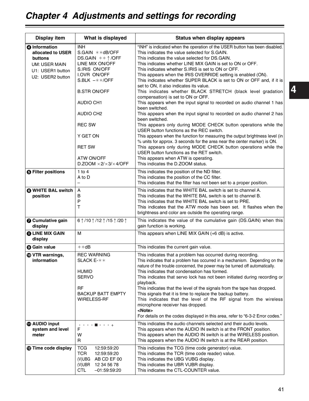
8 LINE MIX GAIN

M


This appears when LINE MIX GAIN (+6 dB) is active.


display


9 Gain value

¢¢dB


This indicates the current gain value.


: VTR warnings,

REC WARNING

This indicates that a problem has occurred during recording.


information

SLACK E-¢¢

This indicates that a problem has occurred in a mechanism. Depending on the


nature of the trouble concerned, the power may be turned off automatically.


HUMID


This indicates that condensation has formed.


SERVO

This indicates that servo lock has not been initiated during recording or


playback.


RF


This indicates that the level of the signals from the tape has dropped.


BACKUP BATT EMPTY

This signals that it is time to replace the backup battery.


WIRELESS-RF

This indicates that the level of the RF signal from the wireless


microphone receiver has dropped.


<Note>


For details on the codes displayed in this area, refer to “6-3-2 Error codes.”


; AUDIO input

-------+

This indicates the audio channels selected and their audio levels.


system and level

F


This appears when the AUDIO IN switch is at the FRONT position.


meter

W


This appears when the AUDIO IN switch is at the WIRELESS position.


R


This appears when the AUDIO IN switch is at the REAR position.


< Time code display

TCG

12:59:59:20

This indicates the TCG (time code generator) value.


TCR

12:59:59:20

This indicates the TCR (time code reader) value.


(V)UBG

AB CD EF 00

This indicates the UBG VUBG display.


(V)UBR

12 34 56 78

This indicates the UBR VUBR display.


CTL

–01:59:59:20

This indicates the CTL-COUNTER value.


41

Page 41
Image 41
Panasonic AJ-HDX400P operating instructions Line MIX Gain

AJ-HDX400P specifications

The Panasonic AJ-HDX400P is a versatile HD camcorder renowned for its exceptional image quality and professional-grade features. This camera is optimized for broadcast and production environments, delivering exceptional performance in a compact design.

One of the standout features of the AJ-HDX400P is its ability to record in multiple formats, including DVCPro HD, DVCPRO50, and DVCPRO. This flexibility allows users to choose the best format for their specific needs, making it suitable for various applications, from documentaries to commercial productions. The camcorder supports high-definition resolutions of up to 1080i, ensuring that the final output meets industry standards.

The camera is equipped with a three-CCD sensor system, which provides outstanding color reproduction and detail. Each CCD chip specializes in capturing specific color information, resulting in rich, vibrant images free from color artifacts. With a resolution of 1280 x 720p and the ability to capture 720p and 1080i formats, the AJ-HDX400P excels in delivering superior image clarity and fluid motion.

In addition to its recording capabilities, the AJ-HDX400P features advanced image processing capabilities. The camera utilizes a high-quality digital signal processor, which ensures that noise reduction is effectively handled, particularly in low-light conditions. This feature is crucial for producing clean and polished footage without compromising quality.

The Panasonic camcorder also boasts an extensive range of connectivity options. Users can benefit from HD-SDI and analog outputs, allowing for versatile connections to monitors and other recording devices. The presence of IEEE 1394 for digital output further enhances its compatibility with various editing systems, streamlining the post-production workflow.

Another notable characteristic of the AJ-HDX400P is its ergonomic design. It is built for extensive usage, featuring a lightweight yet durable chassis. The camcorder has an adjustable viewfinder and an intuitive user interface that make it easy to operate, even in high-pressure shooting environments.

Furthermore, the AJ-HDX400P supports a range of professional accessories, including lenses, microphones, and battery packs, enhancing its functionality for different shooting conditions. This adaptability makes it a reliable choice for videographers and production houses looking for a high-quality recording solution.

In summary, the Panasonic AJ-HDX400P stands out as a feature-rich, professional HD camcorder that combines advanced imaging technology, versatile recording formats, and user-friendly design, making it ideal for a wide array of filming scenarios. Its robustness and exceptional performance solidify its position as a reliable tool in the hands of creative professionals.