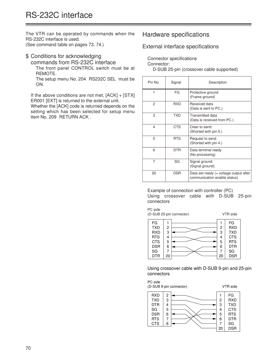
AJ-SD955Bp specifications
The Panasonic AJ-SD955BP is a professional-grade digital camcorder that has captured the interest of many videography and broadcasting professionals. Known for its advanced features and robust design, this camcorder is particularly well-suited for ENG (Electronic News Gathering) and other broadcast applications.One of the standout features of the AJ-SD955BP is its ability to record in both standard and high-quality digital formats. This flexibility allows videographers to choose the best format for their needs. The camcorder supports the DVCPRO digital format, which is renowned for its high-quality imaging and efficient compression, making it ideal for professional use. Additionally, it is equipped to handle standard definitions as well, making it versatile for various production environments.
The AJ-SD955BP utilizes a 1/3-inch 3-CCD sensor system, delivering exceptional color fidelity and sharpness. The three charge-coupled devices capture red, green, and blue images separately, resulting in vibrant imagery and accurate color reproduction. This technology is crucial for professionals looking to achieve high-quality visuals in their productions.
Another notable characteristic of the AJ-SD955BP is its ergonomic design. The camcorder is built for extended use, featuring a compact body that is lightweight yet durable. The intuitive controls and adjustable viewfinder enhance usability, allowing operators to focus on shooting without distraction. This design consideration is vital for fieldwork, where comfort and ease of operation can significantly impact productivity.
In terms of connectivity, the AJ-SD955BP offers various output options, including IEEE 1394 (FireWire) for easy data transfer to editing systems. This connectivity ensures that professionals can streamline their workflows without compromising quality or efficiency. Additionally, the camcorder comes with multiple input options for external audio components, ensuring high-quality sound capture alongside the visuals.
The AJ-SD955BP is also equipped with advanced features such as built-in digital effects and customizable settings, allowing operators to create unique visual styles. The camera’s built-in image stabilizer further enhances the recording quality by reducing unwanted shakes and vibrations, a crucial feature for handheld shooting.
In conclusion, the Panasonic AJ-SD955BP camcorder is a sophisticated tool for professional videographers. With its high-quality imaging capabilities, user-friendly design, and versatile connectivity options, it's an excellent choice for those in the broadcasting and production industry seeking reliability and performance in their gear.

