Controls and their functions
Front Panel | Top Panel |
1
5
4 | 6 |
32
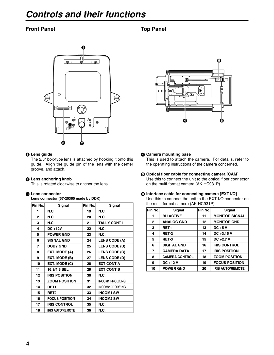
1Lens guide
The 2/3z
2Lens anchoring knob
This is rotated clockwise to anchor the lens.
3Lens connector
Lens connector
Pin No. | Signal | Pin No. | Signal |
|
|
|
|
1 | N.C. | 19 | N.C. |
|
|
|
|
2 | N.C. | 20 | N.C. |
3 | N.C. | 21 | TALLY CONT1 |
|
|
|
|
4 | DC +12V | 22 | N.C. |
|
|
|
|
5 | POWER GND | 23 | N.C. |
6 | SIGNAL GND | 24 | LENS CODE (A) |
|
|
|
|
7 | DOBY GND | 25 | LENS CODE (B) |
|
|
|
|
8 | EXT. MODE (A) | 26 | LENS CODE (C) |
9 | EXT. MODE (B) | 27 | LENS CODE (D) |
|
|
|
|
10 | EXT. MODE (C) | 28 | EXT CONT A |
|
|
|
|
11 | 16:9/4:3 SEL | 29 | EXT CONT B |
12 | IRIS POSITION | 30 | N.C. |
|
|
|
|
13 | ZOOM POSITION | 31 | INCOM1 PROD/ENG |
|
|
|
|
14 | RET1 | 32 | INCOM2 PROD/ENG |
15 | RET2 | 33 | INCOM1 SW |
|
|
|
|
16 | FOCUS POSITION | 34 | INCOM2 SW |
|
|
|
|
17 | IRIS CONTROL | 35 | N.C. |
18 | IRIS AUTO/REMOTE | 36 | N.C. |
4Camera mounting base
This is used to attach the camera. For details, refer to the operating instructions of the camera concerned.
5Optical fiber cable for connecting camera [CAM]
Use this to connect the unit to the optical fiber connector on the
6Interface cable for connecting camera [EXT I/O]
Use this to connect the unit to the EXT I/O connector on the
Pin No. | Signal | Pin No. | Signal |
|
|
|
|
1 | BU ACTIVE | 11 | MONITOR SIGNAL |
2 | ANALOG GND | 12 | MONITOR GND |
|
|
|
|
3 | 13 | DC +5 V | |
|
|
|
|
4 | 14 | DC +3.15 V | |
5 | 15 | DC +2.7 V | |
|
|
|
|
6 | DIGITAL GND | 16 | IRIS CONTROL |
|
|
|
|
7 | CAMERA DATA | 17 | IRIS POSITION |
8 | CAMERA CONTROL | 18 | ZOOM POSITION |
|
|
|
|
9 | DC +12 V | 19 | FOCUS POSITION |
|
|
|
|
10 | POWER GND | 20 | IRIS AUTO/REMOTE |
|
|
|
|
4