■INSTALLING THE DEVICE DRIVER
This section describes how to install the device driver used with the USB image transfer program for the
1 Insert the
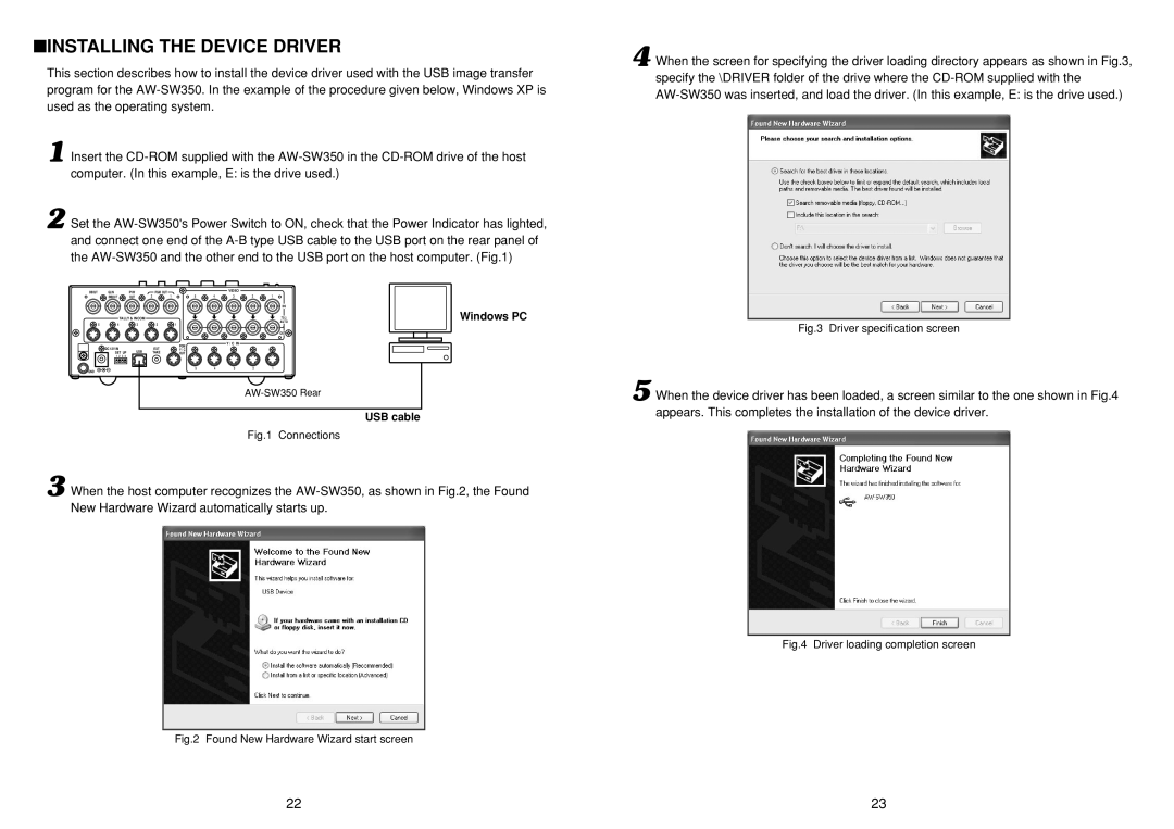
2 Set the
BBOUT | GLIN |
|
|
| PVW |
| PGM OUT |
|
| VIDEO |
|
|
|
| /BBOUT |
|
|
| OUT | 2 | 1 | 5 | 4 | 3 | 2 | 1 |
|
|
|
|
|
|
|
|
|
|
|
|
| IN | Windows PC |
|
| TALLY & INCOM |
|
|
|
|
|
| AUTO | ||||
|
|
|
|
|
|
|
|
|
|
|
| 75 Ω |
|
5 | 4 |
|
|
| 3 |
| 2 | 1 |
|
|
|
|
|
|
|
|
|
|
|
|
|
|
|
|
| OUT |
|
|
|
|
|
|
|
|
| PGM |
| Y / C IN |
|
|
|
| DC 12V IN |
|
|
|
|
| EXT |
|
|
|
|
| |
|
|
|
| USB |
| Y / C |
|
|
|
|
| ||
| SET UP |
| TAKE | OUT |
|
|
|
|
| ||||
| 1 | 2 | 3 | 4 |
|
|
|
|
|
|
|
|
|
|
|
|
|
|
|
|
| 5 | 4 | 3 | 2 | 1 |
|
GND
USB cable
Fig.1 Connections
3 When the host computer recognizes the
Fig.2 Found New Hardware Wizard start screen
4 When the screen for specifying the driver loading directory appears as shown in Fig.3, specify the \DRIVER folder of the drive where the
Fig.3 Driver specification screen
5 When the device driver has been loaded, a screen similar to the one shown in Fig.4 appears. This completes the installation of the device driver.
Fig.4 Driver loading completion screen
22 | 23 |
