MAJOR OPERATING CONTROLS AND THEIR FUNCTIONS
■TOP (CONTROL PANEL)
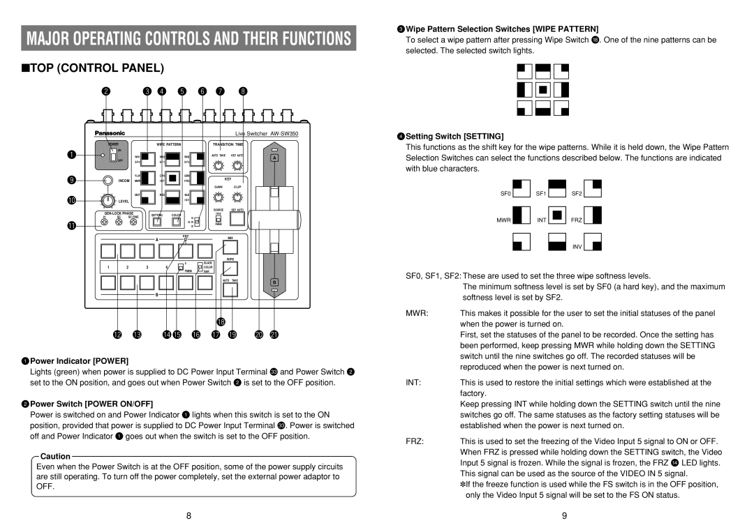
EWipe Pattern Selection Switches [WIPE PATTERN]
To select a wipe pattern after pressing Wipe Switch y. One of the nine patterns can be selected. The selected switch lights.
POWER
ON
WH1
OFFS F 0
YLW
INCOM MWR
WIPE PATTERN
WH2 |
|
|
| WH3 |
|
|
S F 1 |
|
|
| S F 2 |
|
|
|
|
|
|
|
|
|
|
|
|
|
|
|
|
|
|
|
|
|
| |
CYN |
|
|
| GRN |
|
|
|
|
|
|
| ||
I N T |
|
|
| F R Z |
|
|
|
|
|
|
| ||
|
|
|
|
|
|
|
|
|
|
|
|
|
|
Live Switcher
TRANSITION TIME
AUTO TAKE | KEY AUTO | A |
|
|
KEY
GAIN CLIP
RSetting Switch [SETTING]
This functions as the shift key for the wipe patterns. While it is held down, the Wipe Pattern Selection Switches can select the functions described below. The functions are indicated with blue characters.
|
| MGT | RED | BLE |
|
|
|
| LEVEL |
| I N V |
|
|
| |
|
| SOURCE | KEY AUTO |
| |||
SETTING | COLOR | I N 5 |
|
| |||
H | SC | SC FINE |
|
|
| ||
| N |
|
|
| |||
|
|
|
|
|
|
| |
|
|
|
| N / R | FMEM |
|
|
|
|
|
| R |
|
| |
|
|
|
|
|
|
| |
|
|
| A | FRZ | MIX |
| |
|
|
|
|
| |||
|
|
|
|
|
|
| |
|
|
|
|
| WIPE |
| |
1 | 2 | 3 | 4 | 5 | BLACK |
|
|
FMEM | COLOR |
|
| ||||
|
|
|
| BAR |
|
| |
|
|
|
|
| AUTO | TAKE | B |
|
|
|
|
|
|
| |
|
|
| B |
|
|
|
|
QPower Indicator [POWER]
Lights (green) when power is supplied to DC Power Input Terminal L and Power Switch W set to the ON position, and goes out when Power Switch W is set to the OFF position.
WPower Switch [POWER ON/OFF]
Power is switched on and Power Indicator Q lights when this switch is set to the ON position, provided that power is supplied to DC Power Input Terminal L. Power is switched off and Power Indicator Q goes out when the switch is set to the OFF position.
Caution
Even when the Power Switch is at the OFF position, some of the power supply circuits are still operating. To turn off the power completely, set the external power adaptor to OFF.
SF0 |
|
| SF1 |
|
|
| SF2 |
| |
|
|
|
|
|
|
|
|
|
|
MWR |
|
| INT |
|
|
| FRZ |
|
|
|
|
|
|
|
|
| |||
|
|
|
|
|
| ||||
|
|
|
|
|
|
| INV |
|
|
|
|
|
|
|
|
|
|
| |
|
|
|
|
|
|
|
|
| |
SF0, SF1, SF2: These are used to set the three wipe softness levels.
| The minimum softness level is set by SF0 (a hard key), and the maximum |
| softness level is set by SF2. |
MWR: | This makes it possible for the user to set the initial statuses of the panel |
| when the power is turned on. |
| First, set the statuses of the panel to be recorded. Once the setting has |
| been performed, keep pressing MWR while holding down the SETTING |
| switch until the nine switches go off. The recorded statuses will be |
| reproduced when the power is next turned on. |
INT: | This is used to restore the initial settings which were established at the |
| factory. |
| Keep pressing INT while holding down the SETTING switch until the nine |
| switches go off. The same statuses as the factory setting statuses will be |
| established when the power is next turned on. |
FRZ: | This is used to set the freezing of the Video Input 5 signal to ON or OFF. |
| When FRZ is pressed while holding down the SETTING switch, the Video |
| Input 5 signal is frozen. While the signal is frozen, the FRZ w LED lights. |
| This signal can be used as the source of the VIDEO IN 5 signal. |
| ✽If the freeze function is used while the FS switch is in the OFF position, |
| only the Video Input 5 signal will be set to the FS ON status. |
8 | 9 |