BB-HCM581A, BB-HCM580A specifications
The Panasonic BB-HCM580A and BB-HCM581A are part of Panasonic’s elite line of outdoor network cameras designed for versatile surveillance in various environments. These models stand out for their remarkable image quality, user-friendly features, and robust performance in challenging conditions.Both models are equipped with a high-resolution 1/4-inch CCD sensor that provides clear video images in vibrant colors, ensuring effective monitoring both during the day and at night. With a resolution of up to 640x480 pixels, they deliver crisp images, making it easier to identify subjects and capture important details.
One of the key features of the BB-HCM580A and BB-HCM581A is their advanced Intelligent Auto mode, which adjusts exposure and focus automatically. This functionality enhances image quality in varied lighting conditions, making them highly effective for outdoor use. The cameras also include a built-in infrared illuminator, which allows for clear night vision, with a range of up to 15 meters, providing around-the-clock monitoring capabilities.
Both models support Motion Detection technology, which enables the cameras to send alerts and notifications when motion is detected within the field of view. This feature is crucial for security applications, as it allows users to respond promptly to potential threats. The cameras also come with a built-in web server, allowing for easy remote access through standard web browsers. This integration enables users to view live feeds from their cameras anytime and anywhere, making them ideal for business and home security.
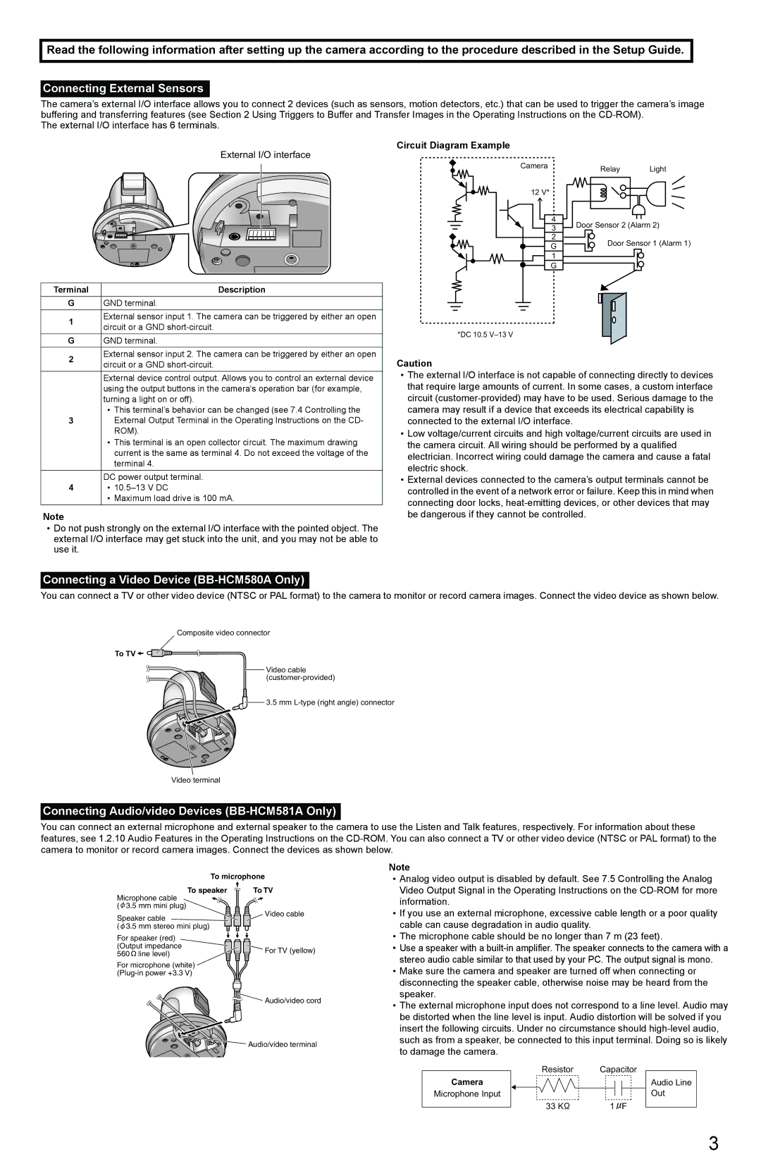
Moreover, the BB-HCM581A model includes an added benefit of two-way audio capability, allowing users to communicate through the camera. This can be particularly useful for interacting with visitors or for deterrence against potential intruders.
Both models are built to withstand outdoor conditions, featuring a durable chassis that meets IP55 standards for water and dust resistance. This construction ensures reliable performance, regardless of weather conditions, from heavy rains to extreme sunlight exposure.
In conclusion, the Panasonic BB-HCM580A and BB-HCM581A offer a comprehensive solution for outdoor surveillance needs. Their high-quality imaging, intelligent features, and rugged design make them suitable for various applications, ensuring safety and security for both residential and commercial properties. With their user-friendly interfaces and advanced capabilities, these cameras stand out as a formidable choice for anyone seeking reliable outdoor surveillance.

