E
N
G
L
I
S
HCautions:
25 | ≥This product is designed to operate of a 12 V DC, negative ground battery system. | |
≥To prevent damage to the unit, be sure to follow the connection diagram below. | ||
| ||
| ≥Remove approx. 5 mm of protective covering from the ends of the leads before connecting. | |
| ≥Do not insert the power connector into the unit until the wiring is completed. | |
| ≥Be sure to insulate any exposed wires from a possible | |
| and keep cable terminals free from touching any metal parts. | |
| ≥Remember, if your car has a drive computer or a navigation computer, the data of its memory may be | |
| erased when the battery terminals are disconnected. | |
| ≥All other installation methods require the use of dedicated metal fittings. Consult with a qualified servicing | |
| engineer or your dealer if other method are required. |
Accessory used for wiring | No. | Item | Q’ty |
| |||
|
|
|
|
| 6 | Power connector | 1 |
|
|
|
|
E
N
G
L
I
S
H
26
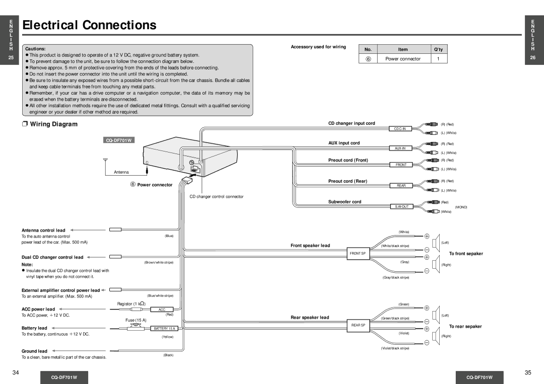
❐ Wiring Diagram |
Antenna
6 Power connector
CD changer control connector
Antenna control lead |
|
To the auto antenna control | (Blue) |
power lead of the car. (Max. 500 mA) |
|
CD changer input cord
AUX input cord
Preout cord (Front)
Preout cord (Rear)
Subwoofer cord
Front speaker lead
(R) (Red)
(L) (White)
(R) (Red)
(L) (White)
![]() (R) (Red)
(R) (Red)
FRONT
![]() (L) (White)
(L) (White)
![]() (R) (Red)
(R) (Red)
REAR
| (L) (White) |
| (Red) |
(MONO) |
![]() (White)
(White)
(White)
+
(Left)
(White/black stripe)
-
FRONT SP
To front sepaker
Dual CD changer control lead
Note:
≥Insulate the dual CD changer control lead with vinyl tape when you do not connect it.
External amplifier control power lead ![]()
To an external amplifier. (Max. 500 mA)
ACC power lead
(Brown/white stripe)
(Blue/white stripe)
Registor (1 k≠)
ACC
+
(Gray)
(Right)
-
(Gray/black stripe)
(Green)
+
To ACC power, _12 V DC.
(Red)
Rear speaker lead
(Green/black stripe)
(Left)
Battery lead
To the battery, continuous _12 V DC.
Ground lead
To a clean, bare metallic part of the car chassis.
Fuse (15 A)
BATTERY 15 A
(Yellow)
(Black)
REAR SP
-
+To rear sepaker
(Violet)
(Right)
-
(Violet/black stripe)
34
35