Installation Guide
Preparation
●Before installation, check the radio operation with antenna and speakers.
●Disconnect the cable from the negative
●Unit should be installed in a horizontal position with the front end up at a convenient angle, but not more than 30°.
E
N
G
L
I
S
H
10
Caution:
For installation to cars with trip or navigational computers, all electronic memory settings previously registered in the computer will be lost when the battery terminal is disconnected. For this type of car, battery could not be disconnected. Therefore, extra care should be taken to prevent short circuitting.
In-dash Installation
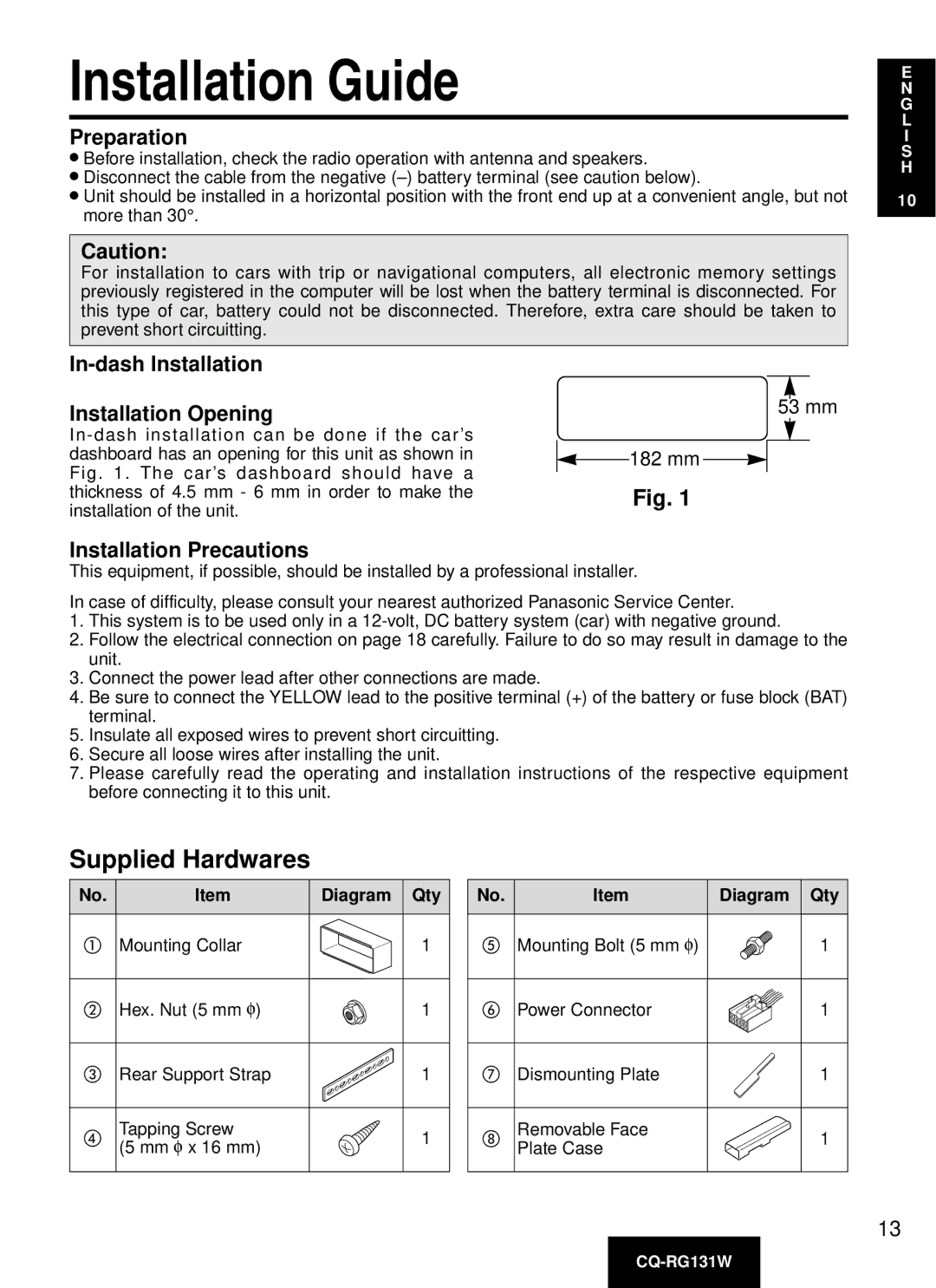
Installation Opening
Installation Precautions
53 mm
 182 mm

Fig. 1
This equipment, if possible, should be installed by a professional installer.
In case of difficulty, please consult your nearest authorized Panasonic Service Center.
1.This system is to be used only in a
2.Follow the electrical connection on page 18 carefully. Failure to do so may result in damage to the unit.
3.Connect the power lead after other connections are made.
4.Be sure to connect the YELLOW lead to the positive terminal (+) of the battery or fuse block (BAT) terminal.
5.Insulate all exposed wires to prevent short circuitting.
6.Secure all loose wires after installing the unit.
7.Please carefully read the operating and installation instructions of the respective equipment before connecting it to this unit.
Supplied Hardwares
No. | Item | Diagram Qty | |
Mounting Collar | 1 | ||
Hex. Nut (5 mm φ ) | 1 | ||
Rear Support Strap | 1 | ||
Tapping Screw | 1 | ||
(5 mm φ | x 16 mm) | ||
| |||
No. | Item | Diagram Qty |
| Mounting Bolt (5 mm φ ) | 1 |
| Power Connector | 1 |
| Dismounting Plate | 1 |
| Removable Face | 1 |
| Plate Case | |
|
|
13