E
N
G
L
I
S
H
15
Electrical Connection
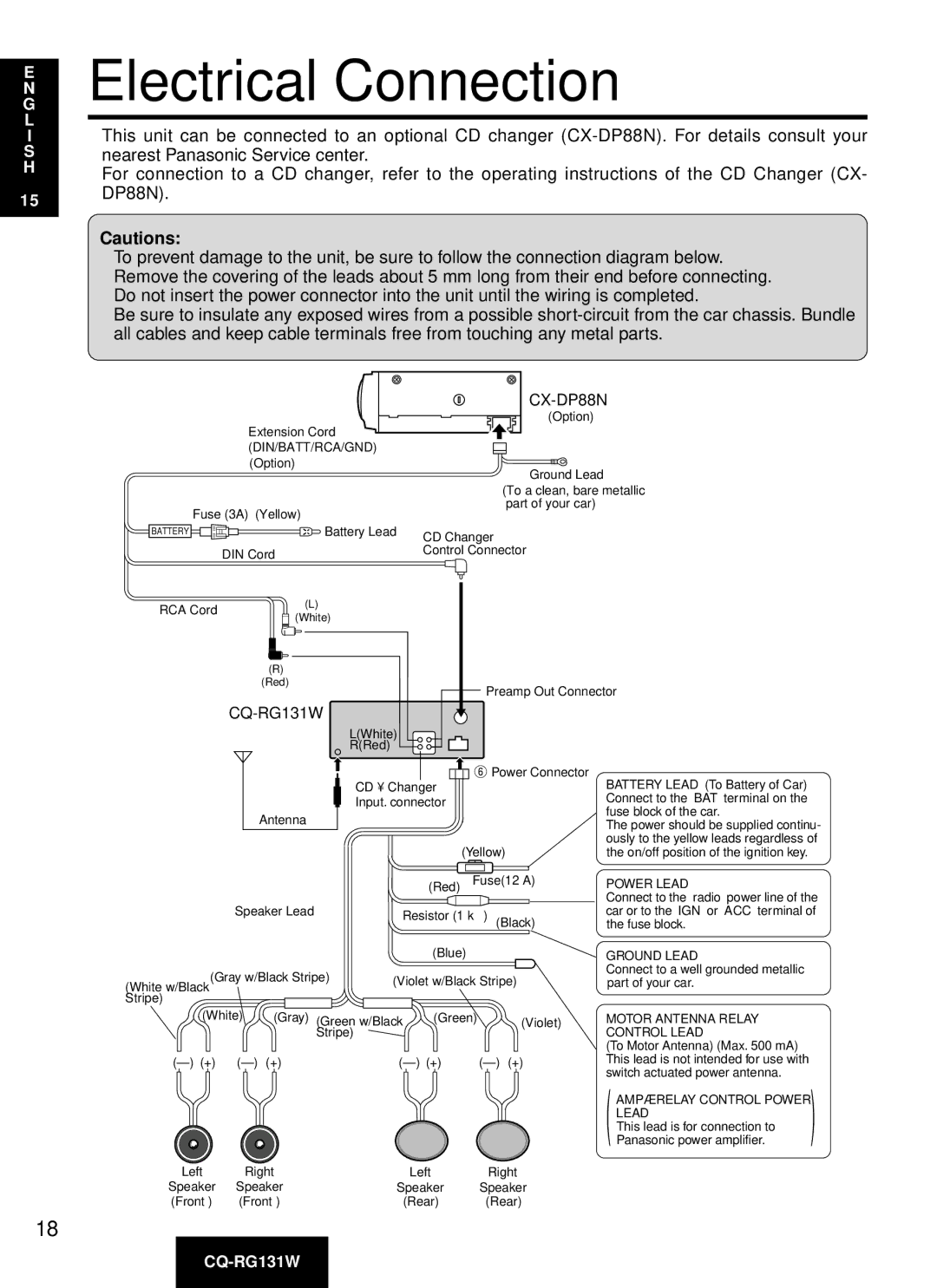
●This unit can be connected to an optional CD changer
●For connection to a CD changer, refer to the operating instructions of the CD Changer (CX- DP88N).
Cautions:
●To prevent damage to the unit, be sure to follow the connection diagram below.
●Remove the covering of the leads about 5 mm long from their end before connecting.
●Do not insert the power connector into the unit until the wiring is completed.
●Be sure to insulate any exposed wires from a possible
CX-DP88N
(Option)
Extension Cord (DIN/BATT/RCA/GND) (Option)
Ground Lead
(To a clean, bare metallic
part of your car)
Fuse (3A) (Yellow)
BATTERY |
| Battery Lead | CD Changer |
| DIN Cord |
| Control Connector |
|
|
|
RCA Cord | (L) | |
(White) | ||
| ||
| (R) | |
| (Red) |
CQ-RG131W
Antenna
Speaker Lead
(Gray w/Black Stripe)
(White w/Black Stripe)
| L(White) |
|
|
|
|
|
|
|
| Preamp Out Connector | ||||||||||||
|
|
|
|
|
|
|
|
| ||||||||||||||
|
|
|
|
|
|
| ||||||||||||||||
|
|
|
|
|
|
| ||||||||||||||||
| R(Red) |
|
|
|
|
|
|
|
| Power Connector | BATTERY LEAD (To Battery of Car) | |||||||||||
|
|
|
|
|
|
|
|
|
|
| ||||||||||||
|
|
|
|
|
|
|
|
|
|
|
|
|
|
|
|
|
|
| ||||
|
|
|
|
|
|
|
|
|
|
|
|
|
|
|
|
|
|
| ||||
| CD • Changer |
|
|
|
|
|
|
|
| |||||||||||||
| Input. connector | Connect to the “BAT” terminal on the | ||||||||||||||||||||
| fuse block of the car. | |||||||||||||||||||||
|
|
|
|
|
|
|
|
|
|
|
|
|
|
|
|
|
|
|
|
|
| |
|
|
|
|
|
|
|
|
|
|
|
|
|
|
|
|
|
|
|
|
|
| The power should be supplied continu- |
|
|
|
|
|
|
|
|
|
|
|
|
|
|
|
|
|
|
|
|
|
| |
|
|
|
|
|
|
|
|
|
|
|
|
|
|
|
|
|
|
|
|
|
| ously to the yellow leads regardless of |
|
|
|
|
|
|
|
|
|
|
|
|
|
|
|
|
|
|
|
|
|
| |
|
|
|
|
|
|
|
|
|
|
|
|
|
| (Yellow) | the on/off position of the ignition key. | |||||||
|
|
|
|
|
|
|
|
|
|
|
|
|
|
|
|
|
|
|
|
| ||
|
|
|
|
|
|
|
| (Red) Fuse(12 A) | POWER LEAD | |||||||||||||
|
|
|
|
|
| |||||||||||||||||
|
|
|
|
|
|
|
|
|
|
|
|
|
|
|
|
|
|
|
|
|
| Connect to the “radio” power line of the |
|
|
|
| Resistor (1 kΩ ) (Black) | car or to the “IGN” or “ACC” terminal of | |||||||||||||||||
|
|
|
| the fuse block. | ||||||||||||||||||
|
|
|
|
|
|
|
|
|
|
|
|
|
|
|
|
|
|
|
|
|
|
|
|
|
|
|
|
|
|
|
| (Blue) | GROUND LEAD | ||||||||||||
|
|
|
| |||||||||||||||||||
|
|
|
|
|
|
|
|
|
|
|
|
|
|
|
|
|
|
|
|
|
| Connect to a well grounded metallic |
|
|
|
| (Violet w/Black Stripe) | ||||||||||||||||||
|
|
|
| part of your car. | ||||||||||||||||||
|
|
|
|
|
|
|
|
|
|
|
|
|
|
|
|
|
|
|
|
|
|
|
18
(White) | (Gray) | (Green w/Black | (Green) | (Violet) | |
|
|
| Stripe) |
|
|
(+) | (+) | ||||
Left | Right | Left | Right |
Speaker | Speaker | Speaker | Speaker |
(Front ) | (Front ) | (Rear) | (Rear) |
MOTOR ANTENNA RELAY
CONTROL LEAD
(To Motor Antenna) (Max. 500 mA) This lead is not intended for use with switch actuated power antenna.
(AMP·RELAY CONTROL POWER )
LEAD
This lead is for connection to Panasonic power amplifier.