|
|
|
|
| |
|
|
|
|
|
|
Ref. No. 2C | Procedure 2A → 2B → 2C | Removal or attachment of the Gear Box Block. |
| ||
|
| (Removal) |
| ||
|
| 1. | Turn the thrust plate to remove. | ||
|
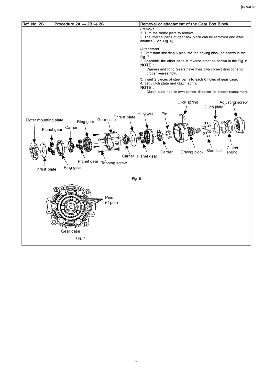
| 2. | The internal parts of gear box block can be removed one after | ||
|
| another. (See Fig. 6) | |||
(Attachment)
1. Start from inserting 6 pins into the driving block as shown in the Fig. 7.
2. Assemble the other parts in reverse order as shown in the Fig. 6.
NOTE :
Carriers and Ring Gears have their own correct directions for proper reassembly.
3. Insert 2 pieces of steel ball into each 6 holes of gear case.
4. Set clutch plate and clutch spring.
NOTE :
Clutch plate has its own correct direction for proper reassembly.
Fig. 6
Fig. 7
5
