EY7440-U1 /
Ref. No. 2D | Procedure 2A → 2B → 2C→ 2D |
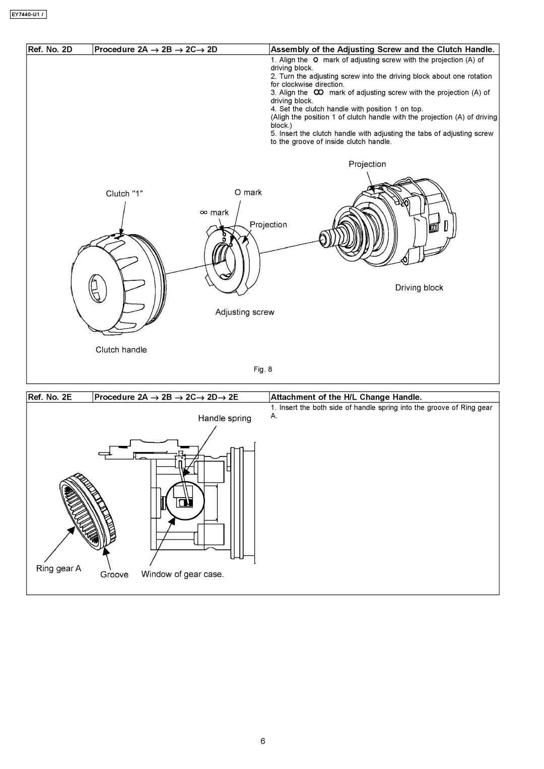
| Assembly of the Adjusting Screw and the Clutch Handle. | ||
|
|
| 1. | Align the | mark of adjusting screw with the projection (A) of |
|
|
| driving block. |
| |
|
| 2. | Turn the adjusting screw into the driving block about one rotation | ||
|
|
| for clockwise direction. | ||
|
| 3. | Align the | mark of adjusting screw with the projection (A) of | |
|
|
| driving block. |
| |
|
| 4. | Set the clutch handle with position 1 on top. | ||
|
|
| (Aligh the position 1 of clutch handle with the projection (A) of driving | ||
|
|
| block.) |
| |
|
| 5. | Insert the clutch handle with adjusting the tabs of adjusting screw | ||
|
|
| to the groove of inside clutch handle. | ||
|
| Fig. 8 |
|
| |
|
|
|
| ||
|
|
|
| ||
Ref. No. 2E | Procedure 2A → 2B → 2C→ 2D→ 2E |
| Attachment of the H/L Change Handle. | ||
|
|
| 1. | Insert the both side of handle spring into the groove of Ring gear | |
|
|
| A. |
|
|
|
|
|
|
|
|
6