Manuals
/
Panasonic
/
Power Tools
/
Cordless Drill
Panasonic
EY7440-U1
specifications
Troubleshooting Guide
Models:
EY7440-U1
1
9
12
12
Download
12 pages
33.45 Kb
5
6
7
8
9
10
11
12
Troubleshooting
Parts list
Page 9
Image 9
EY7440-U1 /
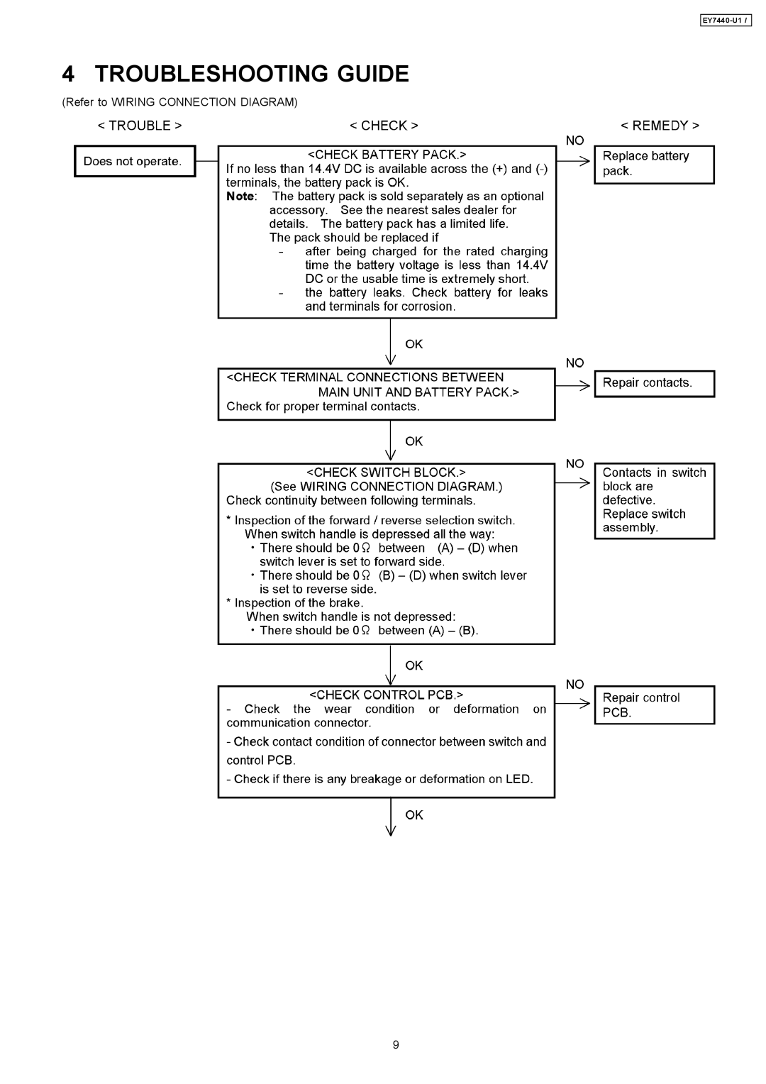
4 TROUBLESHOOTING GUIDE
(Refer to WIRING CONNECTION DIAGRAM)
9
Page 8
Page 10
Page 9
Image 9
Page 8
Page 10
Contents
EY7440-U1
Schematic Diagram Wiring Connection Diagram
DISASSEMBLY/ASSEMBLY Instructions
Ref. No a Procedure 2A Removal of the Housing
EY7440-U1
EY7440-U1
EY7440-U1
For release lever and the hook release lever
Troubleshooting Guide
EY7440-U1
Exploded View
Replacement Parts List
Top
Page
Image
Contents