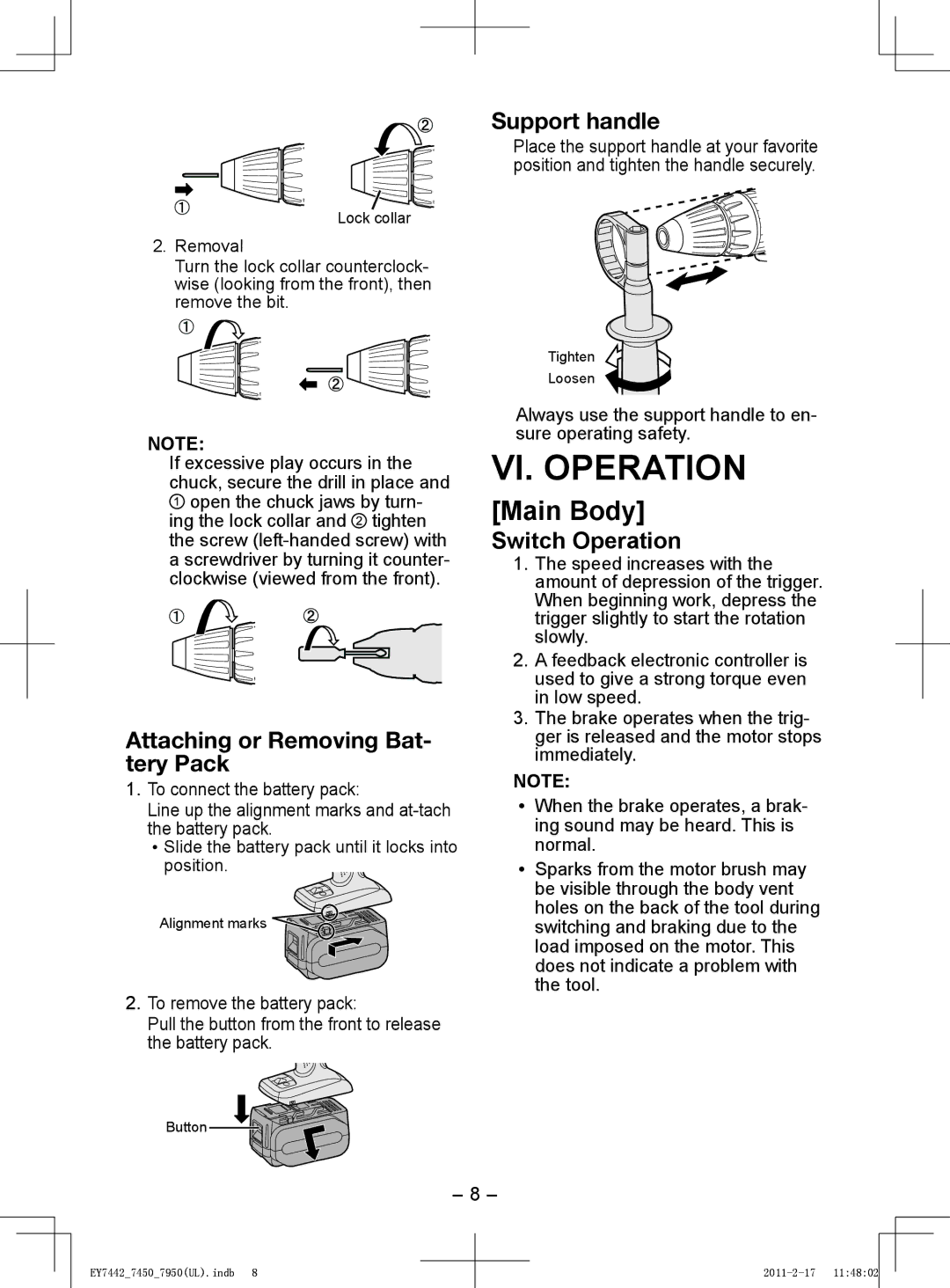
Support handle
Place the support handle at your favorite position and tighten the handle securely.
Lock collar
2. Removal
Turn the lock collar counterclock- wise (looking from the front), then remove the bit.
NOTE:
If excessive play occurs in the chuck, secure the drill in place and ![]() open the chuck jaws by turn- ing the lock collar and
open the chuck jaws by turn- ing the lock collar and ![]() tighten the screw
tighten the screw
Attaching or Removing Bat- tery Pack
1.To connect the battery pack:
Line up the alignment marks and
![]() Slide the battery pack until it locks into position.
Slide the battery pack until it locks into position.
Alignment marks ![]()
2.To remove the battery pack:
Pull the button from the front to release the battery pack.
Tighten
Loosen
Always use the support handle to en- sure operating safety.
VI. OPERATION
[Main Body]
Switch Operation
1.The speed increases with the amount of depression of the trigger. When beginning work, depress the trigger slightly to start the rotation slowly.
2.A feedback electronic controller is used to give a strong torque even in low speed.
3.The brake operates when the trig- ger is released and the motor stops immediately.
NOTE:
•When the brake operates, a brak- ing sound may be heard. This is normal.
•Sparks from the motor brush may be visible through the body vent holes on the back of the tool during switching and braking due to the load imposed on the motor. This does not indicate a problem with the tool.
Button
- 8 -
EY7442_7450_7950(UL).indb 8