Starter Kit Instruction Manual | Description | 20 |
4.5QCL pulser switching unit(LDD100)
4.5.1Description
The switching unit is based on dedicated power
! WARNING !
An important feature of this unit is that both lines going to the laser are ”HOT”, i.e. have a postive voltage respective to the case. this feature should be kept in mind when de- signing the laser holder. This one should be insulated and have a low capacitance(< 100pF) towards the ground.
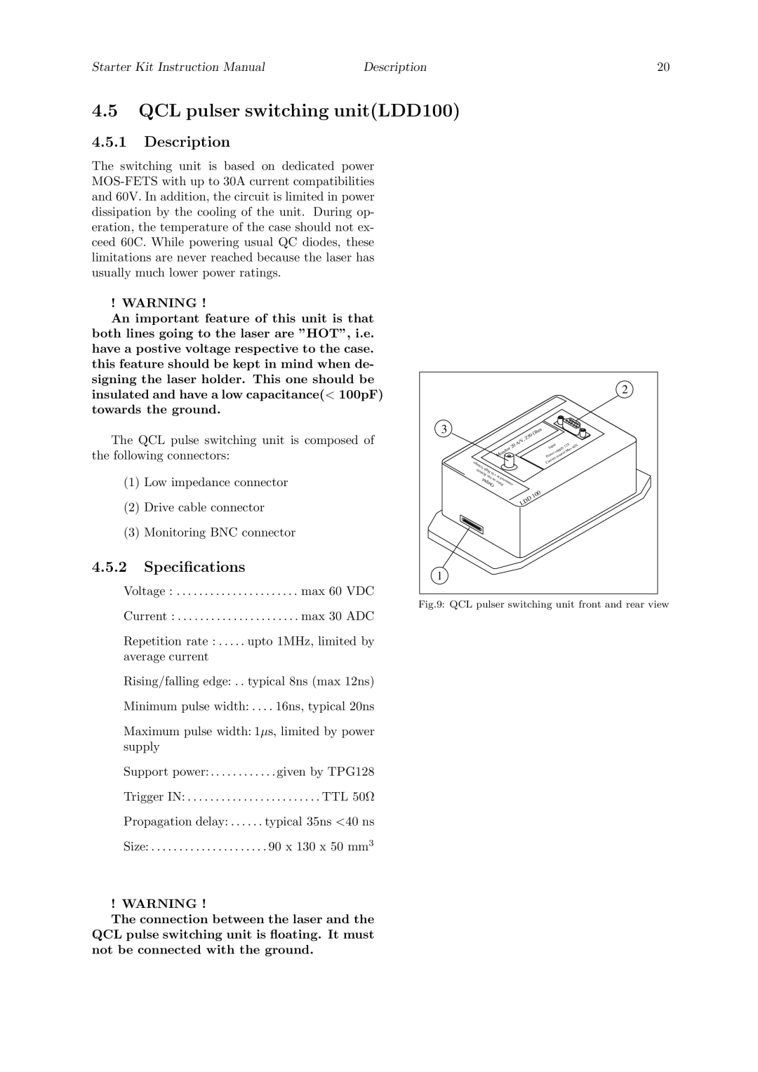
The QCL pulse switching unit is composed of the following connectors:
(1)Low impedance connector
(2)Drive cable connector
(3)Monitoring BNC connector
4.5.2Specifications
Voltage : . . . . . . . . . . . . . . . . . . . . . . max 60 VDC
Current : . . . . . . . . . . . . . . . . . . . . . . max 30 ADC
Repetition rate : . . . . . upto 1MHz, limited by average current
Rising/falling edge: . . typical 8ns (max 12ns)
Minimum pulse width: . . . . 16ns, typical 20ns
Maximum pulse width: 1µs, limited by power supply
Support power: . . . . . . . . . . . . given by TPG128
Trigger IN: . . . . . . . . . . . . . . . . . . . . . . . . TTL 50Ω
Propagation delay: . . . . . . typical 35ns <40 ns
Size: . . . . . . . . . . . . . . . . . . . . . 90 x 130 x 50 mm3
! WARNING !
The connection between the laser and the QCL pulse switching unit is floating. It must not be connected with the ground.
|
|
|
|
|
|
|
|
|
|
|
| 2 |
3 |
|
|
|
|
|
| Z50 | Ohm |
|
|
|
|
|
|
|
|
|
| A/V, |
|
|
|
|
| |
|
|
|
|
| 20 |
|
| Input | 12V | 60V | ||
|
|
|
|
|
|
|
| |||||
|
|
|
| Monitor |
|
|
|
| supply | Max |
| |
|
|
|
|
|
|
|
| Power | control |
|
| |
Voltage |
|
|
|
|
|
|
|
| Current |
|
|
|
High |
|
|
|
|
|
|
|
|
|
| ||
| hi + |
|
|
|
|
|
|
|
|
| ||
Bottom |
| to |
|
|
|
|
|
|
|
| ||
|
| top, on |
|
|
|
|
|
|
|
| ||
Output | Pulseconnected |
|
|
|
|
|
|
| ||||
|
|
|
|
|
| LDD | 100 |
|
|
|
| |
|
|
|
|
|
|
|
|
|
|
| ||
1 |
|
|
|
|
|
|
|
|
|
|
|
|