Starter Kit Instruction Manual | Maintenance | 50 | |
CAUTION ! For the further steps of this |
|
| |
check, limit the positive current to 1 A and |
|
| |
the negative one with 1.2 A by means of the |
|
| |
5 turns potentiometer) |
|
|
|
Temperature limit threshold |
|
|
|
[21] Measure the voltage on pin 2 of U10 |
|
| |
(1). |
|
|
|
Note: The value should be: | 0.7V (= 70 ◦C) | 1 |
|
(If needed, adjust it with the trimmer P9(2)). |
|
| |
[22] Power off the instrument. |
|
| |
Starting the power section of the instru- |
|
| |
ment. |
|
|
|
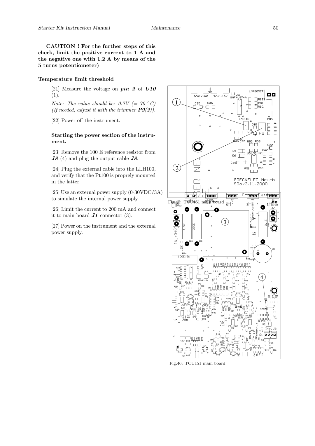
[23] Remove the 100 E reference resistor from |
|
| |
J8 (4) and plug the output cable J8. |
|
| |
[24] Plug the external cable into the LLH100, | 2 |
| |
and verify that the Pt100 is proprely mounted |
|
| |
in the latter. |
|
|
|
[25] Use an external power supply |
|
| |
to simulate the internal power supply. | Fig.45: TCU151 main board |
| |
|
|
| |
[26] Limit the current to 200 mA and connect |
|
| |
it to main board J1 connector (3). |
|
| |
[27] Power on the instrument and the external | 3 |
| |
|
| ||
power supply. |
|
|
|
|
|
| 4 |