Starter Kit Instruction Manual | Maintenance | 41 | |
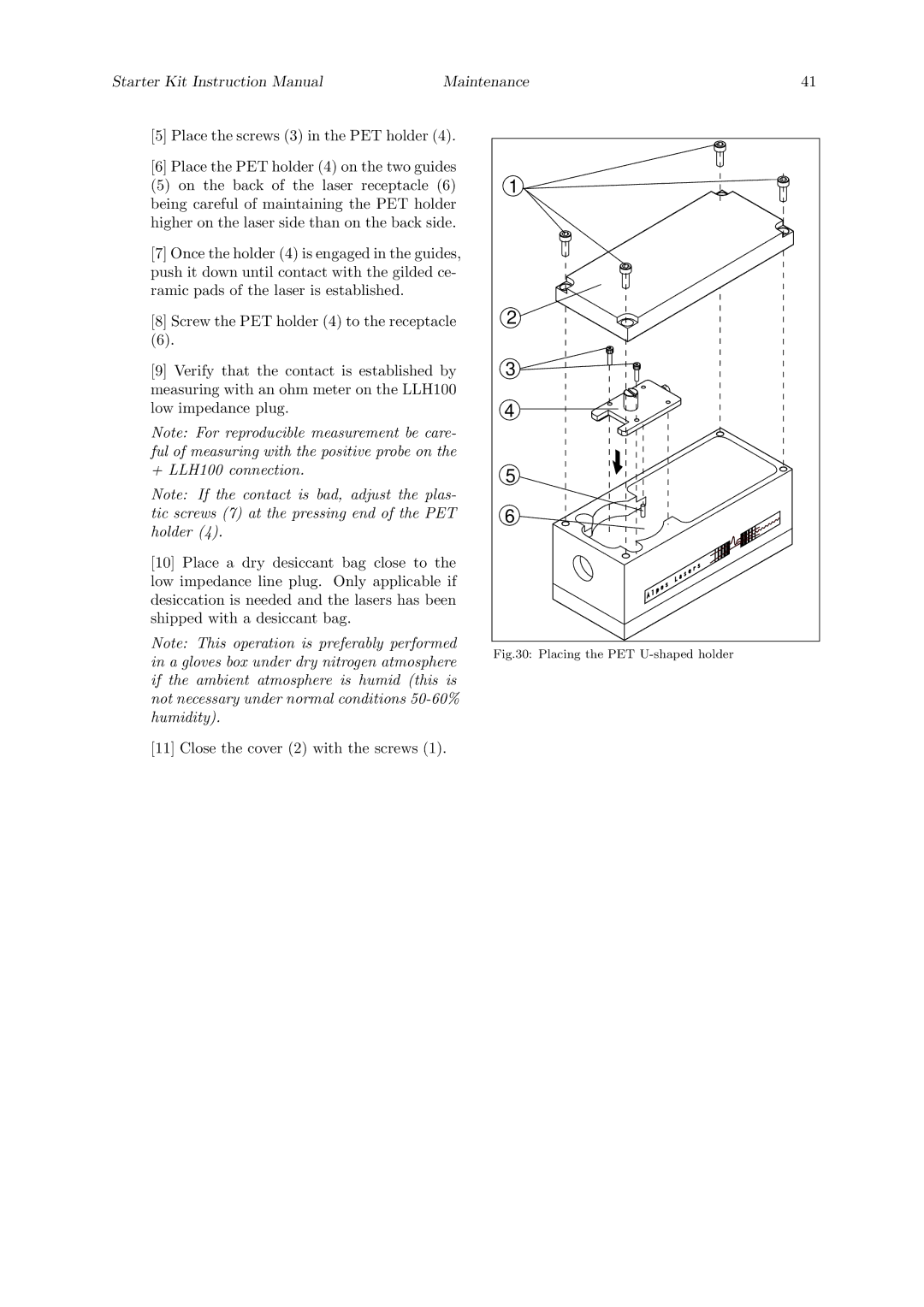
[5] Place the screws (3) in the PET holder (4). |
|
| |
[6] Place the PET holder (4) on the two guides |
|
| |
(5) on the back of the laser receptacle (6) | 1 |
| |
being careful of maintaining the PET holder |
|
| |
higher on the laser side than on the back side. |
|
| |
[7] Once the holder (4) is engaged in the guides, |
|
| |
push it down until contact with the gilded ce- |
|
| |
ramic pads of the laser is established. |
|
|
|
[8] Screw the PET holder (4) to the receptacle | 2 |
| |
(6). |
|
|
|
[9] Verify that the contact is established by | 3 |
| |
measuring with an ohm meter on the LLH100 |
|
| |
low impedance plug. |
| 4 |
|
Note: For reproducible measurement be care- |
|
| |
ful of measuring with the positive probe on the |
|
| |
+ LLH100 connection. |
| 5 |
|
Note: If the contact is bad, adjust the plas- |
|
| |
tic screws (7) at the pressing end of the PET | 6 |
| |
holder (4). |
|
|
|
[10] Place a dry desiccant bag close to the |
|
| |
low impedance line plug. Only applicable if |
|
| |
desiccation is needed and the lasers has been |
|
| |
shipped with a desiccant bag. |
|
|
|
Note: This operation is preferably performed | Fig.30: Placing the PET |
| |
in a gloves box under dry nitrogen atmosphere |
| ||
|
| ||
if the ambient atmosphere is humid (this is |
|
| |
not necessary under normal conditions |
|
| |
humidity). |
|
|
|
[11] Close the cover (2) with the screws (1).