Starter Kit Instruction Manual | Description | 22 |
Duty cycle calculation
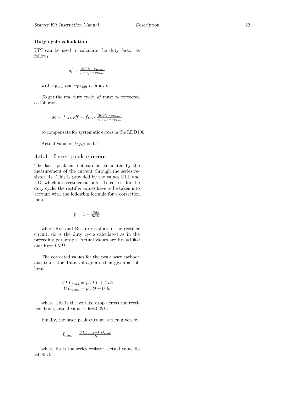
UPI can be used to calculate the duty factor as follows:
df = 2U P I −νP low νP high −νP low
with vP low and vP high as above.
To get the real duty cycle, df must be corrected as follows:
dc = fLDD df = fLDD 2U P I −νP low νP high −νP low
to compensate for systematic errors in the LDD100.
Actual value is fLDD = 1.1
4.6.4Laser peak current
The laser peak current can be calculated by the measurement of the current through the series re- sistor Rs. This is provided by the values ULL and UD, which are rectifier outputs. To correct for the duty cycle, the rectifier values have to be taken into account with the following formula for a correction factor:
p = 1 + RcdcRds
where Rds and Rc are resistors in the rectifier circuit, dc is the duty cycle calculated as in the preceding paragraph. Actual values are Rds=10kΩ and Rc=10MΩ.
The corrected values for the peak laser cathode and transistor drain voltage are then given as fol- lows:
U LLpeak = pU LL + U ds
U Dpeak = pU D + U ds
where Uds is the voltage drop across the recti- fier diode, actual value Uds=0.25V.
Finally, the laser peak current is then given by:
Ipeak = | U LLpeak −U Dpeak | |
Rs | ||
|
where Rs is the series resistor, actual value Rs =0.85Ω.
