Chapter 10
Appendix
10.1Bias Circut (”Bias-T”)
10.1.1General
The
Since tuning of a QC laser is done by changing the temperature of the active zone, the DC Bias cur- rent can be used to control the emission wavelength of the laser via its heating effect. The
10.1.2Description
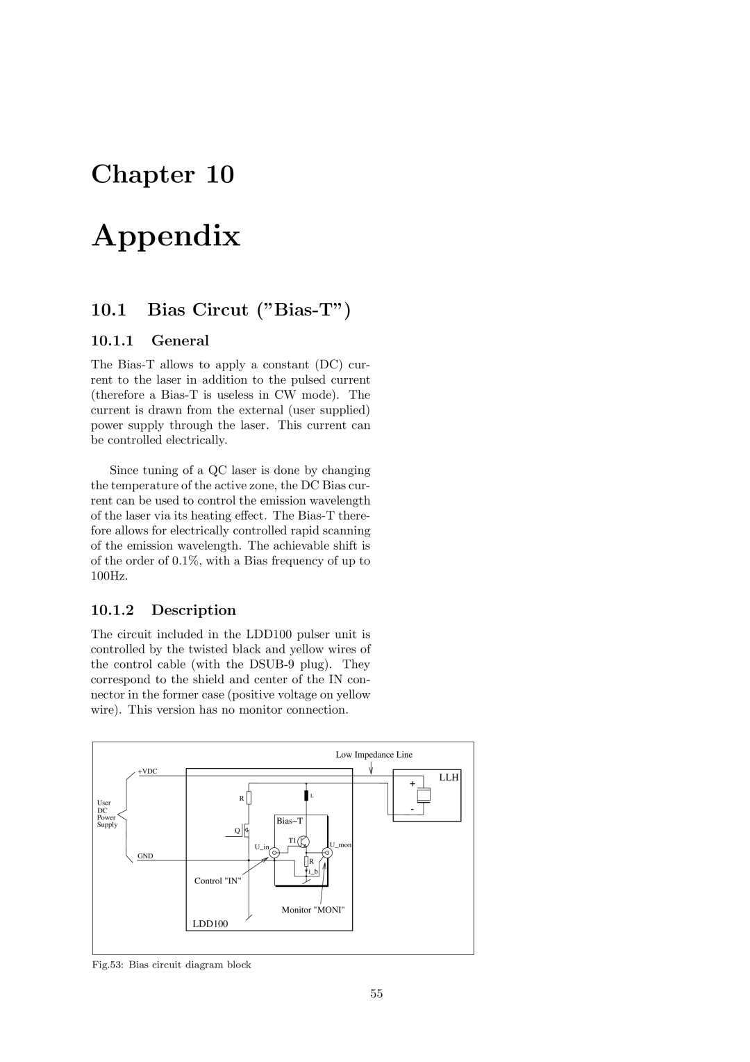
The circuit included in the LDD100 pulser unit is controlled by the twisted black and yellow wires of the control cable (with the
|
|
|
| Low Impedance Line |
| +VDC |
|
| LLH |
|
|
|
| |
| R |
|
| L |
User |
|
|
| |
|
|
|
| |
DC |
|
|
|
|
Power |
|
| Bias−T |
|
Supply |
|
|
| |
Q |
|
|
| |
|
|
|
| |
|
| U_in | T1 | U_mon |
|
|
| ||
|
|
|
| |
| GND |
|
| R |
|
|
|
| |
|
|
|
| i_b |
| Control "IN" |
|
|
|
|
|
| Monitor "MONI" | |
| LDD100 |
|
|
|
Fig.53: Bias circuit diagram block
55