Starter Kit Instruction Manual | Maintenance | 43 |
8.4Calibaration procedures
8.4.1TPG128 calibration
Generalities
The present section describes procedure to be car- ried out for particular calibration of the TPG128.
Before beginning
[1]Switch the instrument OFF.
[2]Remove the cover (1).
[3]Switch the instrument ON.
!WARNING ! Keep in mind that dur- ing the calibration, the instrument is alive (powered on)
Needed material
•1 set of screwdriver.
•1 oscilloscope.
•1 voltmeter.
1 |
|
|
|
|
|
|
|
|
|
|
|
|
|
|
|
|
|
|
|
|
|
|
|
|
|
| O | FF |
| T |
|
|
|
|
|
|
|
|
|
|
|
|
|
|
|
|
|
| |
|
|
|
|
|
|
|
|
|
|
|
|
|
|
|
|
|
|
|
|
|
| |||
|
|
|
|
|
| P |
|
|
|
|
|
|
|
|
|
|
|
|
|
|
|
|
| |
|
|
|
|
|
|
| G | 12 |
|
|
|
|
|
|
|
|
|
|
|
|
|
|
| |
|
| O |
|
|
|
|
|
|
|
|
|
|
|
|
|
|
|
|
|
|
|
| ||
w | N |
|
|
|
|
| 8 | − |
|
|
|
|
|
|
|
|
|
|
|
|
|
| ||
|
|
|
|
|
|
|
| T |
|
|
|
|
|
|
|
|
|
|
|
|
| |||
| er |
|
|
|
|
|
|
|
|
| TL |
|
|
|
|
|
|
|
|
|
|
|
| |
|
|
|
|
| −− |
|
|
|
|
|
| Pu |
|
|
|
|
|
|
|
|
|
| ||
|
|
|
|
|
|
|
|
|
|
|
|
| l |
|
|
|
|
|
|
|
|
| ||
|
|
|
|
| − |
|
|
|
|
| 0. |
| se |
|
|
|
|
|
|
|
| |||
|
| + |
|
|
| − | −− |
|
|
|
|
|
|
| Ge |
|
|
|
|
|
| |||
|
|
|
|
|
|
|
|
|
|
| 2 t |
|
|
|
|
|
|
| ||||||
max |
| 12 |
|
| −− |
|
|
| 0.5 o | 2. | ne |
|
|
|
|
| ||||||||
| 0 |
| V |
|
|
|
| − |
|
| 5 |
| to |
| 2 |
| ra |
|
|
|
| |||
| 60mA |
| V |
|
|
|
|
| Perio |
| to | 1010.5ms |
| tor |
|
|
|
| ||||||
|
|
|
|
|
|
|
|
|
|
| d | − |
|
|
| 5 |
| ms |
| 0 t |
|
|
| |
|
|
|
|
|
|
|
|
|
|
|
|
|
|
|
| ms |
|
|
|
| ||||
|
|
|
|
|
|
|
|
|
|
|
| −− |
|
|
|
|
|
| o | 20 |
| |||
|
|
|
|
|
|
|
|
|
|
|
| 50 | oh | − |
|
|
|
|
|
|
| |||
|
|
|
|
|
|
| Gat |
|
|
|
|
| −− |
|
|
|
|
|
| 0n | ||||
|
|
|
|
|
|
|
|
|
|
|
| ms |
|
| −− |
|
|
|
|
| s | |||
|
|
|
|
|
|
|
| eI |
|
|
|
|
|
|
|
| − |
|
|
|
|
|
| |
|
|
|
|
|
|
|
|
| N |
| Tri |
|
|
|
|
|
|
|
|
|
|
|
|
|
|
|
|
|
|
|
|
|
|
|
|
|
|
|
|
|
| 50 oh | − |
|
|
|
| ||
|
|
|
|
|
|
|
|
|
|
| g O |
|
|
|
|
|
| ms |
|
|
|
| ||
|
|
|
|
|
|
|
|
|
|
|
|
| U |
|
|
|
|
|
| r |
|
|
| |
|
|
|
|
|
|
|
|
|
|
|
|
|
| T |
|
|
|
|
| ati |
| |||
|
|
|
|
|
|
|
|
|
|
|
|
|
|
|
|
|
| O |
| 50 oh |
| on | − | |
|
|
|
|
|
|
|
|
|
|
|
|
|
|
|
|
|
|
|
| ms |
| |||
|
|
|
|
|
|
|
|
|
|
|
|
|
|
|
|
|
| ut |
|
|
|
|
| |
|
|
|
|
|
|
|
|
|
|
|
|
|
|
|
|
|
|
| 1 |
|
|
|
|
|
|
|
|
|
|
|
|
|
|
|
|
|
|
|
|
|
|
|
|
| O |
|
|
|
|
|
|
|
|
|
|
|
|
|
|
|
|
|
|
|
|
|
|
|
| ut |
|
|
| |
|
|
|
|
|
|
|
|
|
|
|
|
|
|
|
|
|
|
|
|
| 2 |
|
|
|
Procedure calibration
The generator should be calibrated as followed:
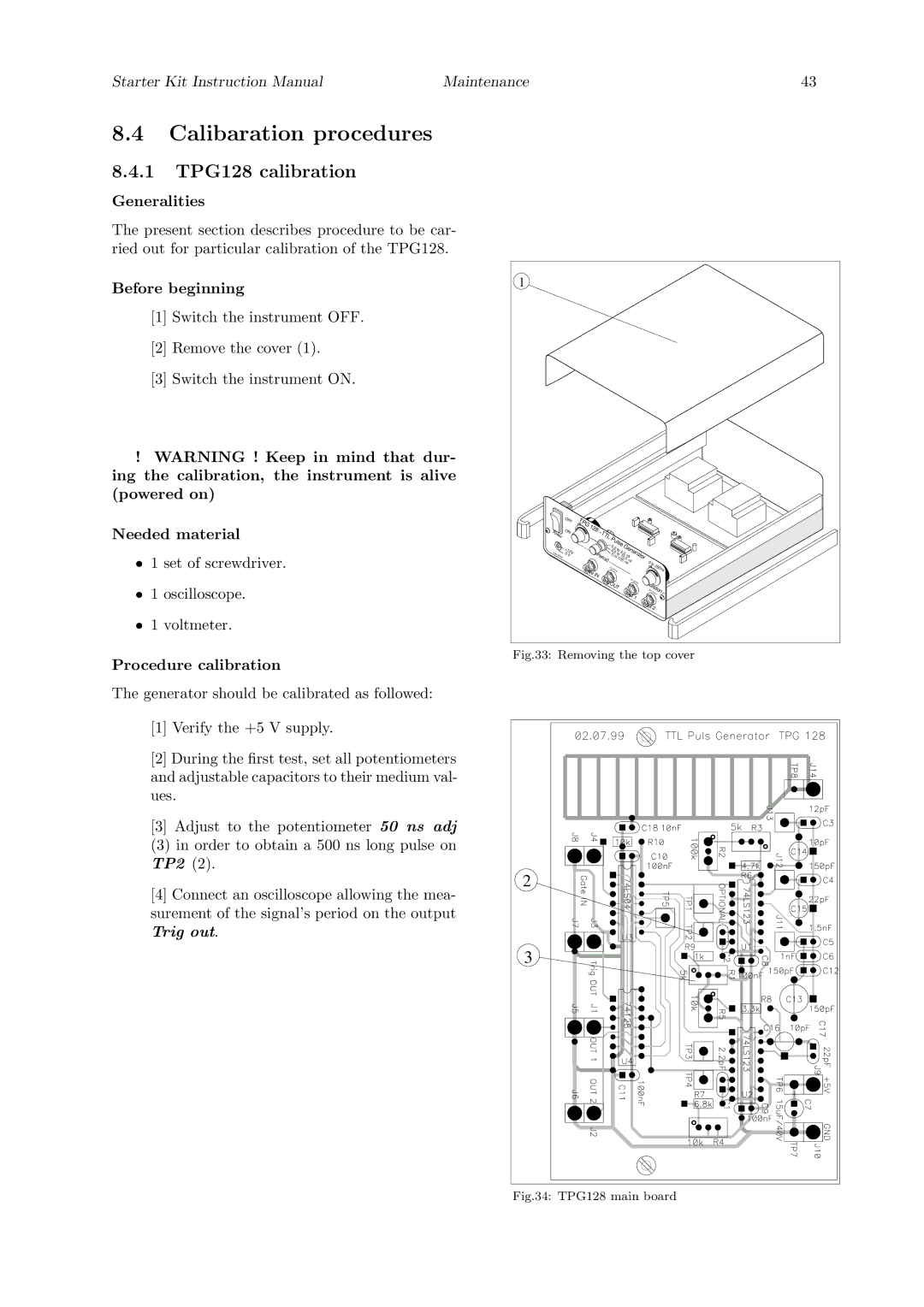
[1]Verify the +5 V supply.
[2]During the first test, set all potentiometers and adjustable capacitors to their medium val- ues.
[3]Adjust to the potentiometer 50 ns adj
(3)in order to obtain a 500 ns long pulse on TP2 (2).
[4]Connect an oscilloscope allowing the mea- surement of the signal’s period on the output Trig out.
Fig.33: Removing the top cover
2 |
3 |