Starter Kit Instruction Manual | Description | 15 |
4.3.4Electrical model
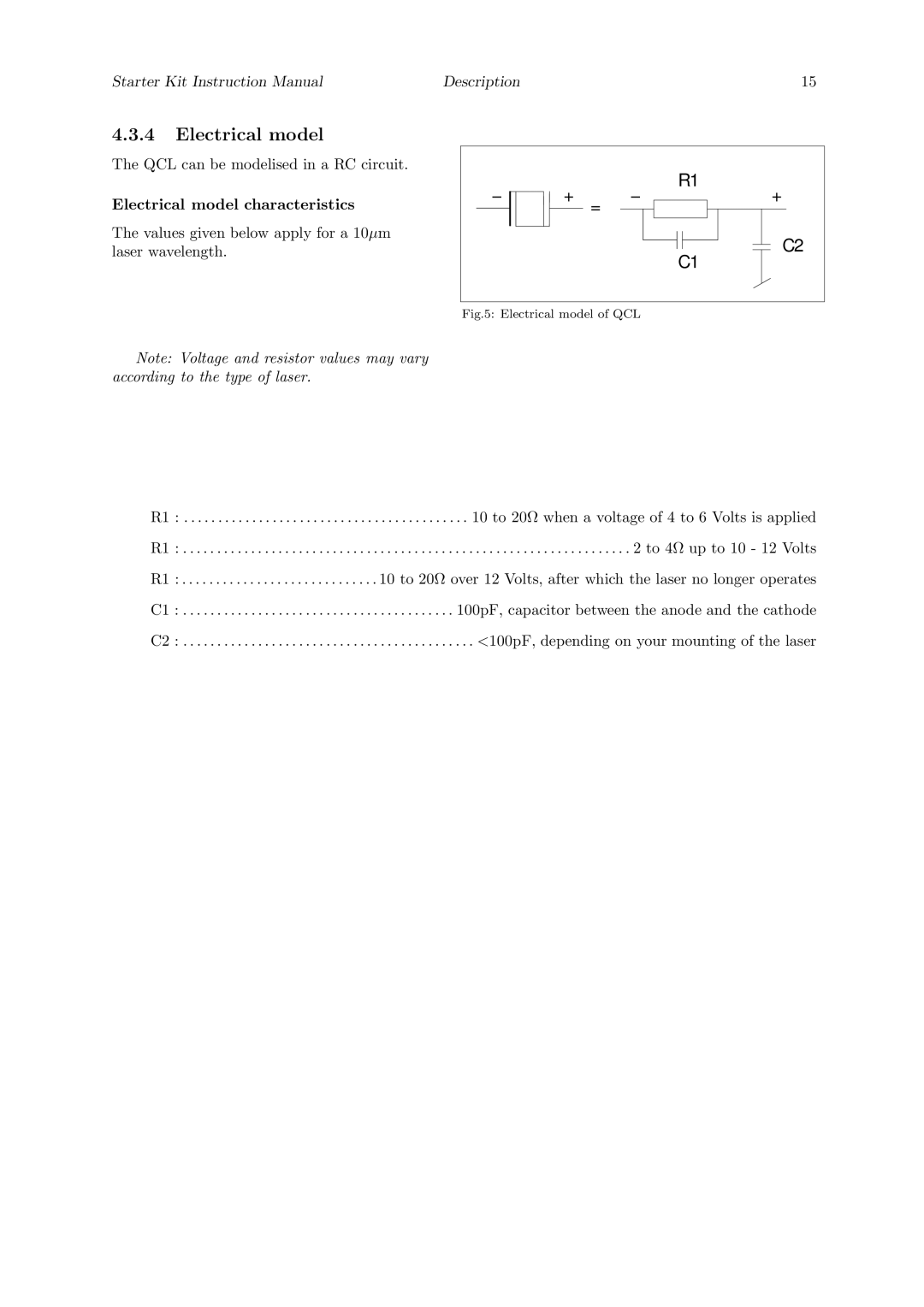
The QCL can be modelised in a RC circuit.
Electrical model characteristics
The values given below apply for a 10µm laser wavelength.
−
+−
=
R1
C1
+
C2
Fig.5: Electrical model of QCL
Note: Voltage and resistor values may vary according to the type of laser.
R1 : . . . . . . . . . . . . . . . . . . . . . . . . . . . . . . . . . . . . . . . . . . 10 to 20Ω when a voltage of 4 to 6 Volts is applied
R1 : . . . . . . . . . . . . . . . . . . . . . . . . . . . . . . . . . . . . . . . . . . . . . . . . . . . . . . . . . . . . . . . . . . 2 to 4Ω up to 10 - 12 Volts
R1 : . . . . . . . . . . . . . . . . . . . . . . . . . . . . . 10 to 20Ω over 12 Volts, after which the laser no longer operates
C1 : . . . . . . . . . . . . . . . . . . . . . . . . . . . . . . . . . . . . . . . . 100pF, capacitor between the anode and the cathode
C2 : . . . . . . . . . . . . . . . . . . . . . . . . . . . . . . . . . . . . . . . . . . . <100pF, depending on your mounting of the laser