Starter Kit Instruction Manual | Description | 24 |
4.7QCL pulser timing unit (TPG128)
4.7.1Description
The QCL pulser timing unit is designed to control the QCL pulser switching unit.
It provides TTL pulses on 50Ω on two indepen- dent outputs. The pulse duration is adjustable from 0 to 200ns. The interval between pulses can be ad- justed between 200ns and 105µs in 3 ranges.
A TTL level Gate in input and Trigger out output have also been included. The trigger pre- cedes the output pulse by about 100ns.
The QCL pulser timing unit includes the +12VDC power supply needed by the QCL pulser switching unit by means of a Lemo 00 connector with the +12V on the centre wire.
|
| O | FF |
| T |
|
|
|
|
|
|
|
|
|
|
|
|
|
|
|
|
|
|
|
| ||
|
|
|
|
|
|
| P | 1 |
|
|
|
|
|
|
|
|
|
|
|
|
|
|
|
|
|
| |
|
|
|
|
|
|
|
| G |
|
|
|
|
|
|
|
|
|
|
|
|
|
|
|
|
|
| |
|
| O |
|
|
|
|
|
| 2 |
|
|
|
|
|
|
|
|
|
|
|
|
|
|
|
|
| |
w | N |
|
|
|
|
|
| 8 | − |
|
|
|
|
|
|
|
|
|
|
|
|
|
|
| |||
|
|
|
|
|
|
|
|
|
| T |
|
|
|
|
|
|
|
|
|
|
|
|
|
| |||
| er |
|
|
|
|
|
|
|
|
|
|
| TL |
|
|
|
|
|
|
|
|
|
|
|
|
| |
|
|
|
|
| −− |
|
|
|
|
|
|
|
| Pu |
|
|
|
|
|
|
|
|
|
| |||
|
|
|
|
|
| − | − | − |
|
|
|
|
|
| 0 |
|
| se | G |
|
|
|
|
|
|
| |
|
| + |
|
|
|
|
| − | −− |
|
|
|
|
|
|
| t |
| e |
|
|
|
|
|
| ||
max |
| 12 |
|
|
|
| − |
|
|
|
| 0.5 o | 2. | ne |
|
|
|
|
|
| |||||||
| 0 |
| V |
|
|
|
|
| Perio |
| 5 |
| to | 2∝ | ra |
|
|
|
|
| |||||||
| 60mA |
| V |
|
|
|
|
|
|
|
|
| to 1010.5 s | tor |
|
|
|
|
| ||||||||
|
|
|
|
|
|
|
|
|
|
|
|
| d | − |
|
|
|
| 5 | ∝s |
| 0 |
|
|
|
| |
|
|
|
|
|
|
|
|
|
|
|
|
|
| − | − |
|
|
| ∝s |
|
| to | 2 |
| |||
|
|
|
|
|
|
|
|
|
|
|
|
|
|
|
|
|
|
|
|
|
|
| |||||
|
|
|
|
|
|
|
| G |
|
|
|
|
| 50 |
|
| −− | − |
|
|
|
|
|
| 0 | ns | |
|
|
|
|
|
|
|
|
|
|
|
|
|
| ohm |
|
|
|
|
|
|
|
| |||||
|
|
|
|
|
|
|
| at |
|
|
|
|
|
|
| s | −− |
|
|
|
|
|
|
| |||
|
|
|
|
|
|
|
|
| e I |
|
|
|
|
|
|
|
|
| − |
|
|
|
|
|
| ||
|
|
|
|
|
|
|
|
|
| N |
| Tri |
|
|
|
|
|
|
|
|
|
|
|
|
|
| |
|
|
|
|
|
|
|
|
|
|
|
|
|
|
|
|
|
|
|
| 50 oh | − |
|
|
|
|
| |
|
|
|
|
|
|
|
|
|
|
|
|
| g | OU |
|
|
|
| ms | D r |
|
|
| ||||
|
|
|
|
|
|
|
|
|
|
|
|
|
| T |
|
|
|
|
|
|
| ||||||
|
|
|
|
|
|
|
|
|
|
|
|
|
|
|
|
|
|
|
|
|
| ati |
| ||||
|
|
|
|
|
|
|
|
|
|
|
|
|
|
|
|
|
|
|
| O |
|
| 50 o |
| o | ||
|
|
|
|
|
|
|
|
|
|
|
|
|
|
|
|
|
|
|
| ut |
|
| hms |
| n | ||
|
|
|
|
|
|
|
|
|
|
|
|
|
|
|
|
|
|
|
|
|
|
|
|
|
|
| |
|
|
|
|
|
|
|
|
|
|
|
|
|
|
|
|
|
|
|
|
| 1 |
|
|
|
|
|
|
|
|
|
|
|
|
|
|
|
|
|
|
|
|
|
|
|
|
|
|
|
| O |
|
|
|
| |
|
|
|
|
|
|
|
|
|
|
|
|
|
|
|
|
|
|
|
|
|
|
| ut |
|
|
| |
|
|
|
|
|
|
|
|
|
|
|
|
|
|
|
|
|
|
|
|
|
|
|
| 2 |
|
|
|
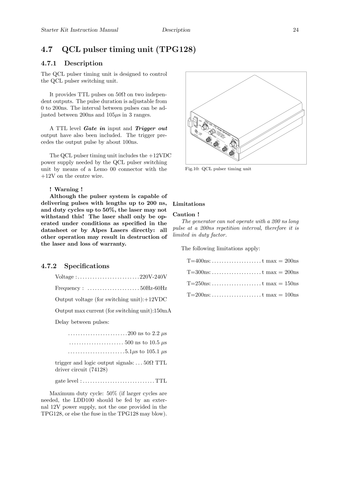
Fig.10: QCL pulser timing unit
! Warning !
Although the pulser system is capable of delivering pulses with lengths up to 200 ns, and duty cycles up to 50%, the laser may not withstand this! The laser shall only be op- erated under conditions as specified in the datasheet or by Alpes Lasers directly: all other operation may result in destruction of the laser and loss of warranty.
4.7.2Specifications
Voltage : . . . . . . . . . . . . . . . . . . . . . . . . .
Frequency : . . . . . . . . . . . . . . . . . . . . .
Output voltage (for switching unit):+12VDC
Output max current (for switching unit):150mA
Delay between pulses:
. . . . . . . . . . . . . . . . . . . . . . . . 200 ns to 2.2 µs
. . . . . . . . . . . . . . . . . . . . . . 500 ns to 10.5 µs
. . . . . . . . . . . . . . . . . . . . . . .5.1µs to 105.1 µs
trigger and logic output signals: . . . 50Ω TTL driver circuit (74128)
gate level : . . . . . . . . . . . . . . . . . . . . . . . . . . . . . TTL
Maximum duty cycle: 50% (if larger cycles are needed, the LDD100 should be fed by an exter- nal 12V power supply, not the one provided in the TPG128, or else the fuse in the TPG128 may blow).
Limitations
Caution !
The generator can not operate with a 200 ns long pulse at a 200ns repetition interval, therefore it is limited in duty factor.
The following limitations apply:
T=400ns: . . . . . . . . . . . . . . . . . . . . t max = 200ns
T=300ns: . . . . . . . . . . . . . . . . . . . . t max = 200ns
T=250ns: . . . . . . . . . . . . . . . . . . . . t max = 150ns
T=200ns: . . . . . . . . . . . . . . . . . . . . t max = 100ns