ADJUSTMENT PROCEDURE
VHF ADJUSTMENTS (CONT’D)
2.Select the low power channel in the middle of the band (Test Ch. 5 - 160.050 MHz). On the computer screen, scroll to “MOD N” if setting narrow band deviation or “MOD W” if setting wideband deviation.
3.Monitor the transmit deviation with a communica- tions monitor set as follows: HPF = Off, LPF = 20 kHz,
4.Key the transmitter using the test cable switch and
set the following maximum deviation by pressing the adjust keys (←/→, PgUp/PgDn, or spacebar/
backspace). Unkey the transmitter.
Wideband (30 kHz) Models - 4.2 kHz Narrow Band (12.5 kHz) Models - 2.1 kHz
5.If the transceiver operates on both narrow and wide band channels, select Test Ch. 7 and also adjust the deviation on that channel (see note in Table
6.4.4 DTCS WAVEFORM ADJUST
1.Select a channel in the middle of the band pro- grammed for DTCS (Test Ch. 8 - 160.050 MHz). On the computer screen, scroll to “DTCS N” if setting a narrow band channel or “DTCS W” if setting a wideband channel.
2.Key the transmitter and view the demodulated sig- nal on the CRT of a communications monitor.
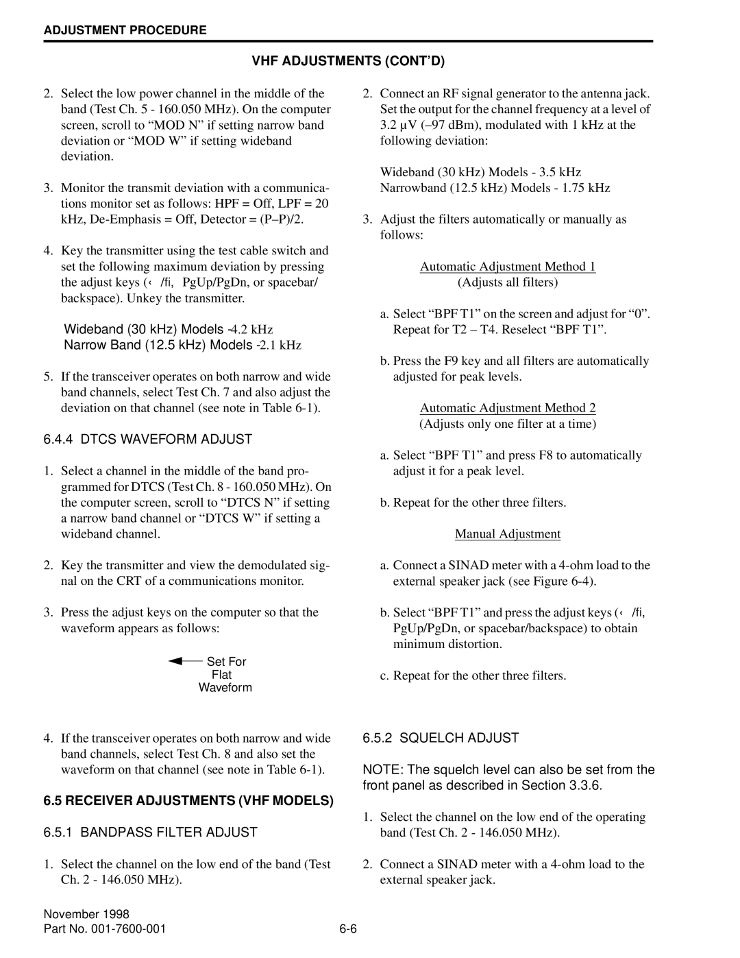
3.Press the adjust keys on the computer so that the waveform appears as follows:
![]() Set For
Set For
Flat
Waveform
4.If the transceiver operates on both narrow and wide band channels, select Test Ch. 8 and also set the waveform on that channel (see note in Table
6.5 RECEIVER ADJUSTMENTS (VHF MODELS)
6.5.1 BANDPASS FILTER ADJUST
1.Select the channel on the low end of the band (Test Ch. 2 - 146.050 MHz).
2.Connect an RF signal generator to the antenna jack. Set the output for the channel frequency at a level of 3.2 µV
Wideband (30 kHz) Models - 3.5 kHz Narrowband (12.5 kHz) Models - 1.75 kHz
3.Adjust the filters automatically or manually as follows:
Automatic Adjustment Method 1
(Adjusts all filters)
a.Select “BPF T1” on the screen and adjust for “0”. Repeat for T2 – T4. Reselect “BPF T1”.
b.Press the F9 key and all filters are automatically adjusted for peak levels.
Automatic Adjustment Method 2 (Adjusts only one filter at a time)
a. Select “BPF T1” and press F8 to automatically adjust it for a peak level.
b. Repeat for the other three filters.
Manual Adjustment
a.Connect a SINAD meter with a
b.Select “BPF T1” and press the adjust keys ( ←/→, PgUp/PgDn, or spacebar/backspace) to obtain minimum distortion.
c.Repeat for the other three filters.
6.5.2 SQUELCH ADJUST
NOTE: The squelch level can also be set from the front panel as described in Section 3.3.6.
1.Select the channel on the low end of the operating band (Test Ch. 2 - 146.050 MHz).
2.Connect a SINAD meter with a
November 1998 |
|
Part No. |