|
|
| PROGRAMMING | |
| Table | |||
|
|
|
| |
Parameter |
| Description |
| |
|
|
| ||
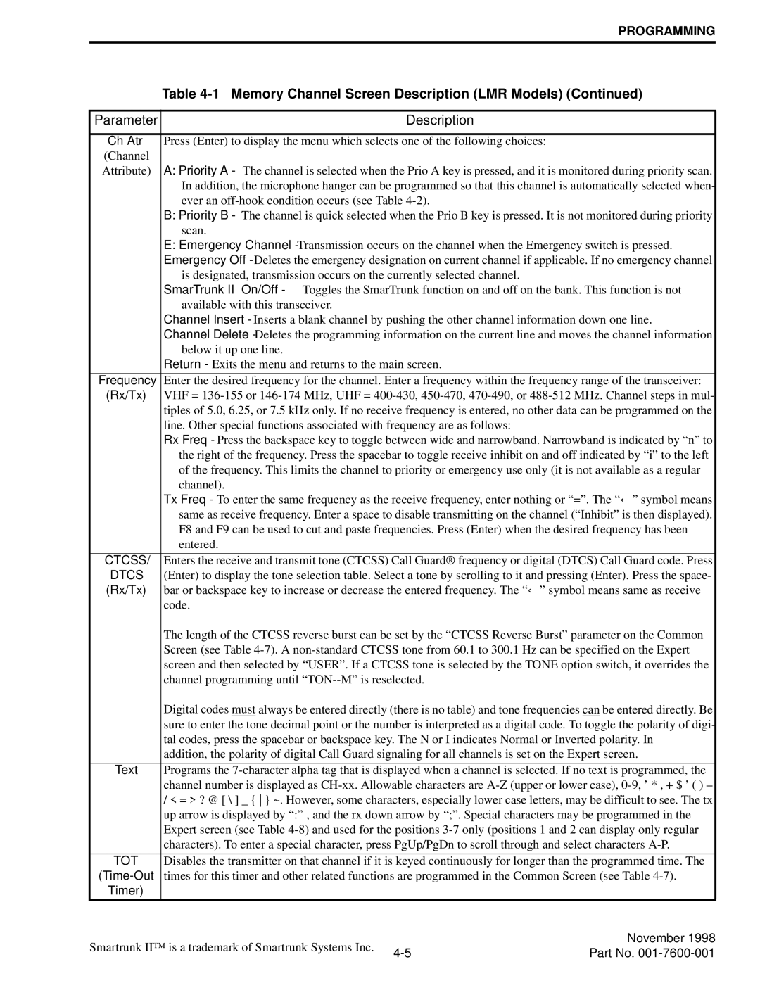
Ch Atr | Press (Enter) to display the menu which selects one of the following choices: |
| ||
(Channel |
|
|
| |
Attribute) | A: Priority A - The channel is selected when the Prio A key is pressed, and it is monitored during priority scan. | |||
| In addition, the microphone hanger can be programmed so that this channel is automatically selected when- | |||
| ever an |
| ||
| B: Priority B - The channel is quick selected when the Prio B key is pressed. It is not monitored during priority | |||
| scan. |
|
| |
| E: Emergency Channel - Transmission occurs on the channel when the Emergency switch is pressed. | |||
| Emergency Off - Deletes the emergency designation on current channel if applicable. If no emergency channel | |||
| is designated, transmission occurs on the currently selected channel. |
| ||
| SmarTrunk II™ On/Off - Toggles the SmarTrunk function on and off on the bank. This function is not | |||
| available with this transceiver. |
|
| |
| Channel Insert - Inserts a blank channel by pushing the other channel information down one line. | |||
| Channel Delete - Deletes the programming information on the current line and moves the channel information | |||
| below it up one line. |
|
| |
| Return - Exits the menu and returns to the main screen. |
| ||
|
| |||
Frequency | Enter the desired frequency for the channel. Enter a frequency within the frequency range of the transceiver: | |||
(Rx/Tx) | VHF = | |||
| tiples of 5.0, 6.25, or 7.5 kHz only. If no receive frequency is entered, no other data can be programmed on the | |||
| line. Other special functions associated with frequency are as follows: |
| ||
| Rx Freq - Press the backspace key to toggle between wide and narrowband. Narrowband is indicated by “n” to | |||
| the right of the frequency. Press the spacebar to toggle receive inhibit on and off indicated by “i” to the left | |||
| of the frequency. This limits the channel to priority or emergency use only (it is not available as a regular | |||
| channel). |
|
| |
| Tx Freq - To enter the same frequency as the receive frequency, enter nothing or “=”. The “ ←” symbol means | |||
| same as receive frequency. Enter a space to disable transmitting on the channel (“Inhibit” is then displayed). | |||
| F8 and F9 can be used to cut and paste frequencies. Press (Enter) when the desired frequency has been | |||
| entered. |
|
| |
|
| |||
CTCSS/ | Enters the receive and transmit tone (CTCSS) Call Guard® frequency or digital (DTCS) Call Guard code. Press | |||
DTCS | (Enter) to display the tone selection table. Select a tone by scrolling to it and pressing (Enter). Press the space- | |||
(Rx/Tx) | bar or backspace key to increase or decrease the entered frequency. The “ ←” symbol means same as receive | |||
| code. |
|
| |
| The length of the CTCSS reverse burst can be set by the “CTCSS Reverse Burst” parameter on the Common | |||
| Screen (see Table | |||
| screen and then selected by “USER”. If a CTCSS tone is selected by the TONE option switch, it overrides the | |||
| channel programming until |
| ||
| Digital codes must always be entered directly (there is no table) and tone frequencies can be entered directly. Be | |||
| sure to enter the tone decimal point or the number is interpreted as a digital code. To toggle the polarity of digi- | |||
| tal codes, press the spacebar or backspace key. The N or I indicates Normal or Inverted polarity. In | |||
| addition, the polarity of digital Call Guard signaling for all channels is set on the Expert screen. | |||
|
| |||
Text | Programs the | |||
| channel number is displayed as | |||
| / < = > ? @ [ \ ] _ { } ~. However, some characters, especially lower case letters, may be difficult to see. The tx | |||
| up arrow is displayed by “:” , and the rx down arrow by “;”. Special characters may be programmed in the | |||
| Expert screen (see Table | |||
| characters). To enter a special character, press PgUp/PgDn to scroll through and select characters | |||
|
| |||
TOT | Disables the transmitter on that channel if it is keyed continuously for longer than the programmed time. The | |||
| times for this timer and other related functions are programmed in the Common Screen (see Table | |||
Timer) |
|
|
| |
|
|
|
| |
Smartrunk II™ is a trademark of Smartrunk Systems Inc. |
| November 1998 | ||
Part No. | ||||
|
| |||