INSTALLATION AND DISASSEMBLY
2.6 TRANSCEIVER DISASSEMBLY
Removing Bottom Cover and Front Panel
1.Remove the bottom cover by removing four screws
(A)as shown in Figure
2.Remove the front panel by removing two screws
(B).
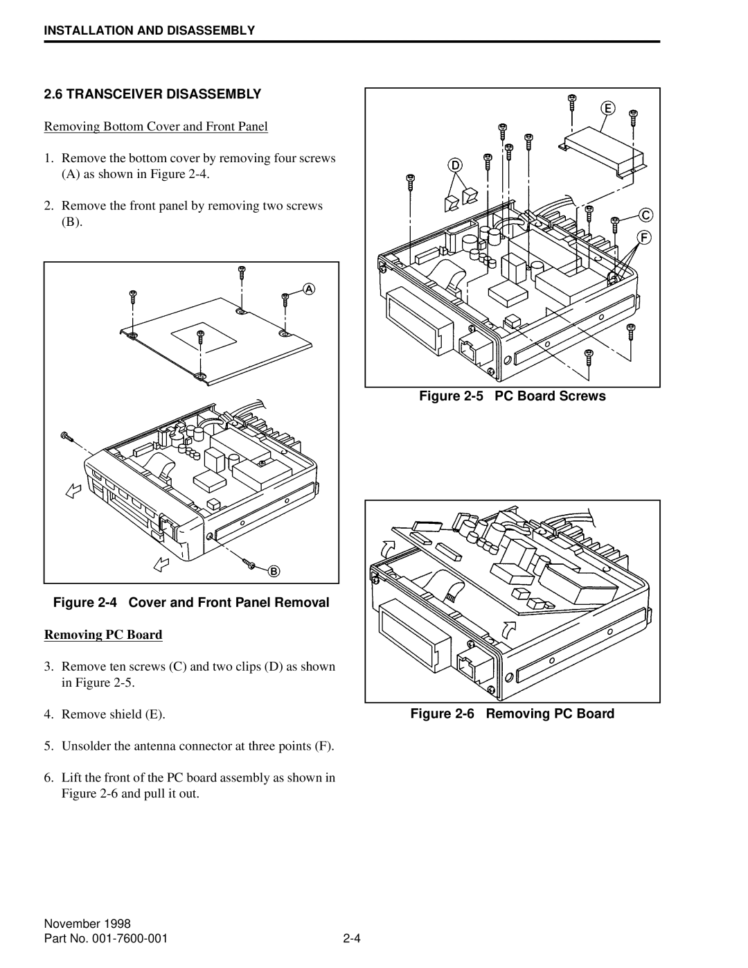
Figure 2-5 PC Board Screws
Figure 2-4 Cover and Front Panel Removal
Removing PC Board
3.Remove ten screws (C) and two clips (D) as shown in Figure
4. Remove shield (E). | Figure |
5.Unsolder the antenna connector at three points (F).
6.Lift the front of the PC board assembly as shown in Figure
November 1998 |
|
Part No. |