ADJUSTMENT PROCEDURE
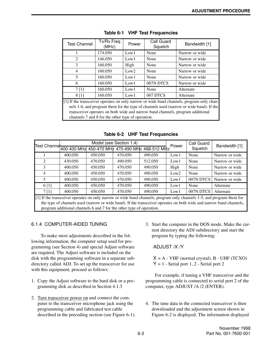
Table 6-1 VHF Test Frequencies
Test Channel | Tx/Rx Freq | Power | Call Guard | Bandwidth [1] | |
(MHz) | Squelch | ||||
|
|
| |||
|
|
|
|
| |
1 | 174.050 | Low1 | None | Narrow or wide | |
|
|
|
|
| |
2 | 146.050 | Low1 | None | Narrow or wide | |
|
|
|
|
| |
3 | 160.050 | High | None | Narrow or wide | |
|
|
|
|
| |
4 | 160.050 | Low2 | None | Narrow or wide | |
|
|
|
|
| |
5 | 160.050 | Low1 | None | Narrow or wide | |
|
|
|
|
| |
6 | 160.050 | Low1 | 007N DTCS | Narrow or wide | |
|
|
|
|
| |
7 [1] | 160.050 | Low1 | None | Alternate | |
|
|
|
|
| |
8 [1] | 160.050 | Low1 | 007 DTCS | Alternate | |
|
|
|
|
|
[1] If the transceiver operates on only narrow or wide band channels, program only chan- nels
Table 6-2 UHF Test Frequencies
Test Channel |
| Model (see Section 1.4) |
| Power | Call Guard | Bandwidth [1] | ||
Squelch | ||||||||
|
|
| ||||||
1 | 400.050 | 450.050 | 470.050 | 490.050 | Low1 | None | Narrow or wide | |
|
|
|
|
|
|
|
| |
2 | 430.050 | 470.050 | 490.050 | 512.050 | Low1 | None | Narrow or wide | |
|
|
|
|
|
|
|
| |
3 | 400.050 | 450.050 | 470.050 | 490.050 | High | None | Narrow or wide | |
|
|
|
|
|
|
|
| |
4 | 400.050 | 450.050 | 470.050 | 490.050 | Low2 | None | Narrow or wide | |
|
|
|
|
|
|
|
| |
5 | 400.050 | 450.050 | 470.050 | 490.050 | Low1 | 007N DTCS | Narrow or wide | |
|
|
|
|
|
|
|
| |
6 [1] | 400.050 | 450.050 | 470.050 | 490.050 | Low1 | None | Alternate | |
|
|
|
|
|
|
|
| |
7 [1] | 400.050 | 450.050 | 470.050 | 490.050 | Low1 | 007N DTCS | Alternate | |
|
|
|
|
|
|
|
| |
[1] If the transceiver operates on only narrow or wide band channels, program only channels
6.1.4 COMPUTER-AIDED TUNING
To make most adjustments described in the fol- lowing information, the computer setup used for pro- gramming (see Section 4) and special Adjust software are required. The Adjust software is included on the disk with the programming software in a separate sub- directory called ADJ. To set up the transceiver for use with this equipment, proceed as follows:
1.Copy the Adjust software to the hard disk or a pro- gramming disk as described in Section 4.1.3
2.Turn transceiver power on and connect the com- puter to the transceiver microphone jack using the programming cable and fabricated test cable described in the preceding section (see Figure
3.Start the computer in the DOS mode. Make the cur- rent directory the ADJ subdirectory and start the program by typing the following:
ADJUST /X /Y
X = A - VHF (normal crystal), B - UHF (TCXO) Y = 1 - Serial port 1, 2 - Serial port 2
For example, if tuning a VHF transceiver and the programming cable is connected to serial port 2 of the computer, type ADJUST /A /2 (ENTER).
4.The tune data in the connected transceiver is then downloaded and the adjustment screen shown in Figure
| November 1998 |
Part No. |
