OPERATION
3.2 CONTROLS AND DISPLAY
3.2.1 FRONT PANEL CONTROLS
Power Switch ( ![]()
![]()
![]()
![]()
![]()
![]() ) - Press this switch to turn power on and press and hold it to turn power off. The trans- ceiver may be programmed so that a password must be entered to allow operation. Refer to Section 3.3.2 for more information.
) - Press this switch to turn power on and press and hold it to turn power off. The trans- ceiver may be programmed so that a password must be entered to allow operation. Refer to Section 3.3.2 for more information.
Volume Up/Down Keys ( ![]()
![]()
![]()
![]()
![]()
![]()
![]()
![]()
![]()
![]() ) - Adjust the vol- ume level up or down in up to 32 steps. The minimum selectable volume level can be set as described in Section 3.3.3.
) - Adjust the vol- ume level up or down in up to 32 steps. The minimum selectable volume level can be set as described in Section 3.3.3.
Up/Down Keys ( ![]()
![]()
![]()
![]()
![]()
![]() ) - These keys may be pro- grammed to select the next higher or lower channel or for other functions. Refer to the descriptions in Section 3.5 for more information.
) - These keys may be pro- grammed to select the next higher or lower channel or for other functions. Refer to the descriptions in Section 3.5 for more information.
Microphone Connector - Connection point for the microphone. Do not connect microphones other than standard microphone P.N.
F1/F2/F3/F4 - These keys can be programmed to con- trol any of the functions described in Section 3.5. Place the applicable included label on the switch to indicate its function.
3.2.2 DISPLAY
Transmit Indicator ( ![]()
![]()
![]()
![]()
![]() ) - Indicates that the trans- mitter is keyed or the
) - Indicates that the trans- mitter is keyed or the
Busy Indicator ( ![]()
![]()
![]()
![]()
![]() ) - Indicates the currently selected channel is busy (see Section 3.4.4).
) - Indicates the currently selected channel is busy (see Section 3.4.4).
Bell Indicator ( ![]()
![]() ) - Appears or flashes when a
) - Appears or flashes when a
Monitor Indicator ( ![]()
![]()
![]()
![]()
![]() ) - Indicates that the monitor mode is enabled. This mode disables coded squelch control so that all messages occurring on the channel are heard. Refer Section 3.4.4 for more information.
) - Indicates that the monitor mode is enabled. This mode disables coded squelch control so that all messages occurring on the channel are heard. Refer Section 3.4.4 for more information.
Display - This
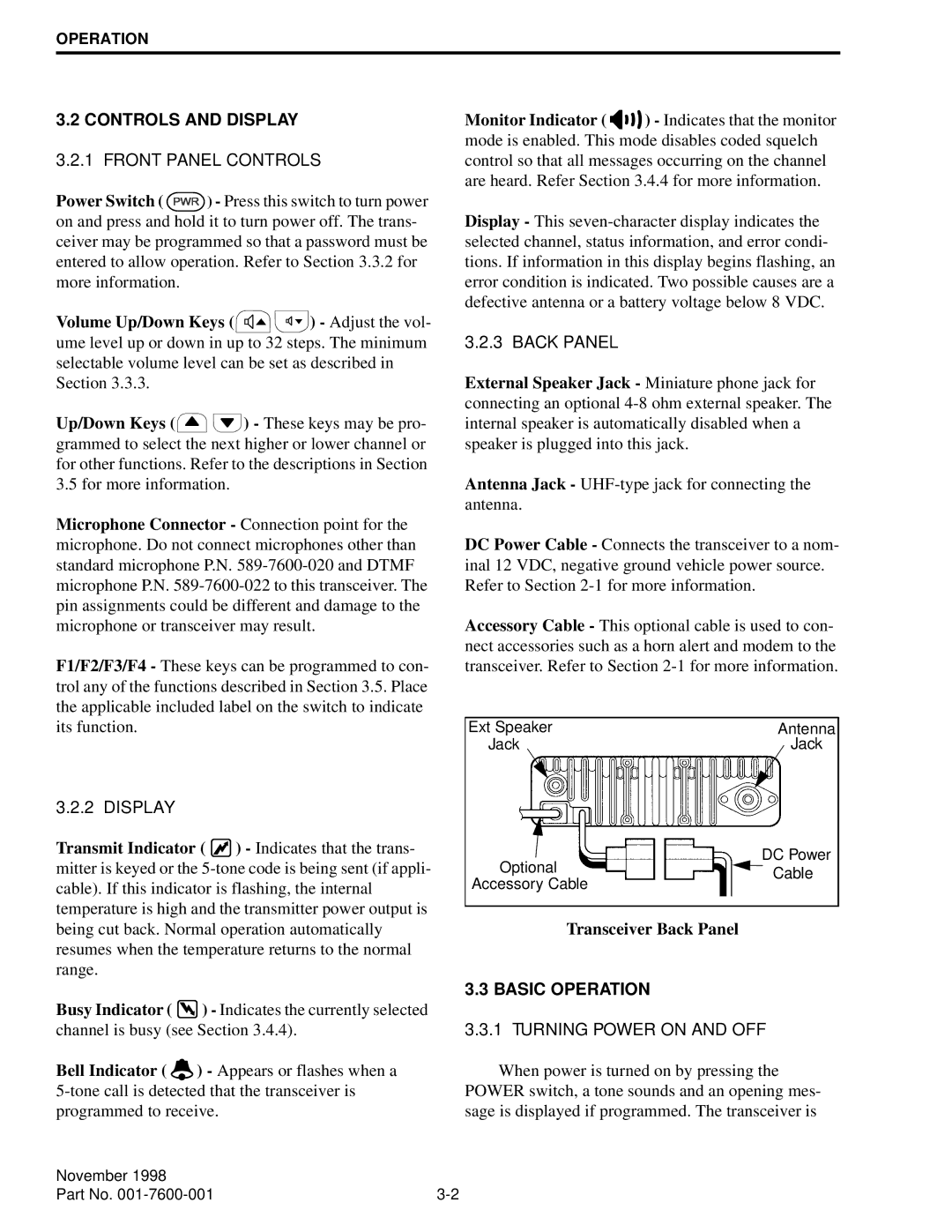
3.2.3 BACK PANEL
External Speaker Jack - Miniature phone jack for connecting an optional
Antenna Jack -
DC Power Cable - Connects the transceiver to a nom- inal 12 VDC, negative ground vehicle power source. Refer to Section
Accessory Cable - This optional cable is used to con- nect accessories such as a horn alert and modem to the transceiver. Refer to Section
Ext Speaker | Antenna |
Jack | Jack |
DC Power
Optional | Cable | |
Accessory Cable | ||
|
Transceiver Back Panel
3.3 BASIC OPERATION
3.3.1 TURNING POWER ON AND OFF
When power is turned on by pressing the POWER switch, a tone sounds and an opening mes- sage is displayed if programmed. The transceiver is
November 1998 |
|
Part No. |