INSTALLATION AND DISASSEMBLY
2.7 2-TONE/5-TONE MODULE INSTALLATION
2.7.1 INSTALLATION PROCEDURE
1.Turn power off and disconnect the power cable.
2.Remove the bottom cover by removing the four screws (A) shown in Figure
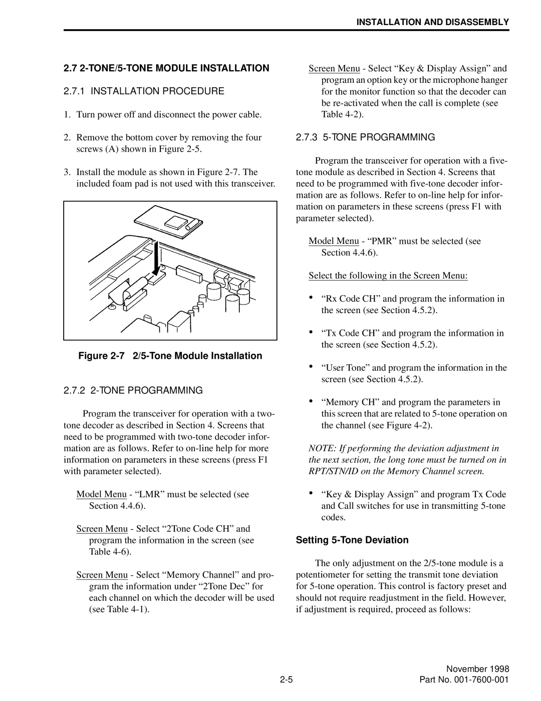
3.Install the module as shown in Figure
Figure 2-7 2/5-Tone Module Installation
2.7.2 2-TONE PROGRAMMING
Program the transceiver for operation with a two- tone decoder as described in Section 4. Screens that need to be programmed with
Model Menu - “LMR” must be selected (see Section 4.4.6).
Screen Menu - Select “2Tone Code CH” and program the information in the screen (see Table
Screen Menu - Select “Memory Channel” and pro- gram the information under “2Tone Dec” for each channel on which the decoder will be used (see Table
Screen Menu - Select “Key & Display Assign” and program an option key or the microphone hanger for the monitor function so that the decoder can be
2.7.3 5-TONE PROGRAMMING
Program the transceiver for operation with a five- tone module as described in Section 4. Screens that need to be programmed with
Model Menu - “PMR” must be selected (see Section 4.4.6).
Select the following in the Screen Menu:
•“Rx Code CH” and program the information in the screen (see Section 4.5.2).
•“Tx Code CH” and program the information in the screen (see Section 4.5.2).
•“User Tone” and program the information in the screen (see Section 4.5.2).
•“Memory CH” and program the parameters in this screen that are related to
NOTE: If performing the deviation adjustment in the next section, the long tone must be turned on in RPT/STN/ID on the Memory Channel screen.
•“Key & Display Assign” and program Tx Code and Call switches for use in transmitting
Setting 5-Tone Deviation
The only adjustment on the
| November 1998 |
Part No. |