VHF (7610) CIRCUIT DESCRIPTION
| Pin | Port | Description |
| No. | Name | |
|
| ||
|
|
|
|
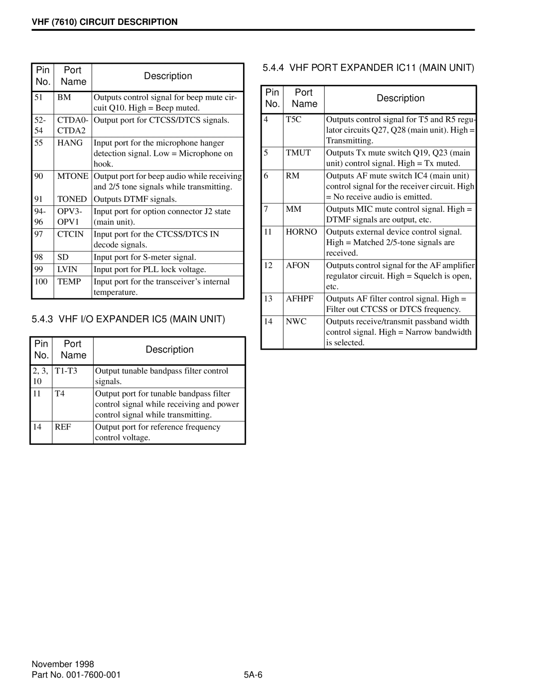
| 51 | BM | Outputs control signal for beep mute cir- |
|
|
| cuit Q10. High = Beep muted. |
|
|
|
|
| 52- | CTDA0- | Output port for CTCSS/DTCS signals. |
| 54 | CTDA2 |
|
|
|
|
|
| 55 | HANG | Input port for the microphone hanger |
|
|
| detection signal. Low = Microphone on |
|
|
| hook. |
|
|
|
|
| 90 | MTONE | Output port for beep audio while receiving |
|
|
| and 2/5 tone signals while transmitting. |
| 91 | TONED | Outputs DTMF signals. |
|
|
|
|
| 94- | OPV3- | Input port for option connector J2 state |
| 96 | OPV1 | (main unit). |
|
|
|
|
| 97 | CTCIN | Input port for the CTCSS/DTCS IN |
|
|
| decode signals. |
|
|
|
|
| 98 | SD | Input port for |
|
|
|
|
| 99 | LVIN | Input port for PLL lock voltage. |
|
|
|
|
| 100 | TEMP | Input port for the transceiver’s internal |
|
|
| temperature. |
|
|
|
|
| 5.4.3 VHF I/O EXPANDER IC5 (MAIN UNIT) | ||
|
|
|
|
| Pin | Port | Description |
| No. | Name | |
|
| ||
|
|
|
|
| 2, 3, | Output tunable bandpass filter control | |
| 10 |
| signals. |
|
|
|
|
| 11 | T4 | Output port for tunable bandpass filter |
|
|
| control signal while receiving and power |
|
|
| control signal while transmitting. |
|
|
|
|
| 14 | REF | Output port for reference frequency |
|
|
| control voltage. |
|
|
|
|
5.4.4 VHF PORT EXPANDER IC11 (MAIN UNIT)
Pin | Port | Description | |
No. | Name | ||
| |||
|
|
| |
4 | T5C | Outputs control signal for T5 and R5 regu- | |
|
| lator circuits Q27, Q28 (main unit). High = | |
|
| Transmitting. | |
|
|
| |
5 | TMUT | Outputs Tx mute switch Q19, Q23 (main | |
|
| unit) control signal. High = Tx muted. | |
|
|
| |
6 | RM | Outputs AF mute switch IC4 (main unit) | |
|
| control signal for the receiver circuit. High | |
|
| = No receive audio is emitted. | |
|
|
| |
7 | MM | Outputs MIC mute control signal. High = | |
|
| DTMF signals are output, etc. | |
|
|
| |
11 | HORNO | Outputs external device control signal. | |
|
| High = Matched | |
|
| received. | |
|
|
| |
12 | AFON | Outputs control signal for the AF amplifier | |
|
| regulator circuit. High = Squelch is open, | |
|
| etc. | |
|
|
| |
13 | AFHPF | Outputs AF filter control signal. High = | |
|
| Filter out CTCSS or DTCS frequency. | |
|
|
| |
14 | NWC | Outputs receive/transmit passband width | |
|
| control signal. High = Narrow bandwidth | |
|
| is selected. | |
|
|
|
November 1998 |
|
Part No. |
