Analogue Signal Processing
FP0 Analogue Units
Features
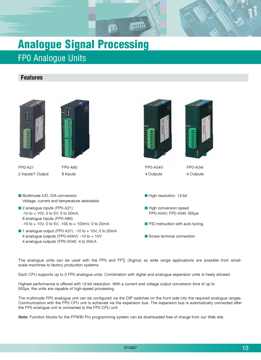
2 Inputs/1 Output | 8 Inputs | 4 Outputs | 4 Outputs |
■ Multimode A/D, D/A conversion | ■ High resolution: |
Voltage, current and temperature selectable |
|
■ 2 analogue inputs | ■ High conversion speed |
8 analogue inputs |
|
■ PID instruction with auto tuning |
■1 analogue output
4 analogue outputs | ■ Screw terminal connection |
4 analogue outputs |
|
The analogue units can be used with the FP0 and FP∑ (Sigma) so wide range applications are possible from small- scale machines to factory production systems.
Each CPU supports up to 3 FP0 analogue units. Combination with digital and analogue expansion units is freely allowed.
Highest performance is offered with
The multimode FP0 analogue unit can be configured via the DIP switches on the front side into the required analogue ranges. Communication with the FP0 CPU unit is achieved via the expansion bus. The expansion bus is automatically connected after the FP0 analogue unit is connected to the FP0 CPU unit.
Note: Function blocks for the FPWIN Pro programming system can be downloaded free of charge from our Web site.
07/2007 | 13 |
|
