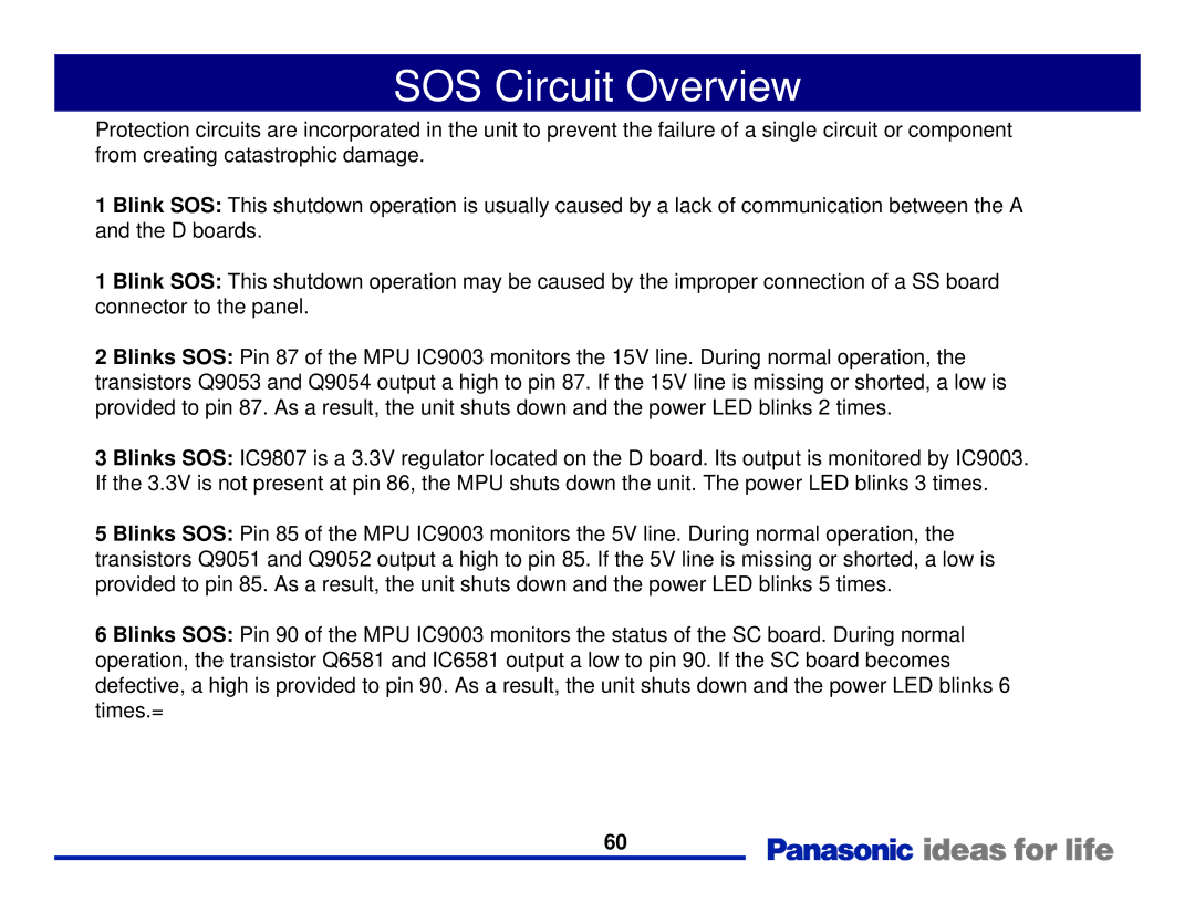
Generation Plasma Display Television specifications
The Panasonic Generation Plasma Display Television, a remarkable innovation in home entertainment technology, has set the standard for high-quality visual experience since its introduction. Renowned for their stunning display quality, these televisions employ advanced plasma technology to deliver vibrant colors, deep blacks, and exceptional contrast ratios. The screens are designed to produce lifelike images, available in various sizes, catering to both casual viewers and dedicated cinephiles.One of the standout features of Panasonic’s plasma TVs is their superior color accuracy. With the ability to reproduce a wide color spectrum, these displays bring scenes to life, making colors appear more vivid and true to the original. The Real Black Drive technology enhances the display's ability to produce deeper blacks, resulting in richer image quality and an overall more immersive viewing experience, especially in dark environments.
In addition to impressive visuals, Panasonic also focuses on audio quality. Many models feature integrated sound systems that complement the stunning visuals, providing clear, balanced sound. For users looking for even more audio fidelity, the televisions are compatible with various external sound systems, enhancing the home theater experience.
The Panasonic Generation Plasma televisions are equipped with advanced connectivity options. HDMI ports, USB inputs, and built-in Wi-Fi functionality allow users to connect a wide range of devices, from gaming consoles to streaming set-top boxes, ensuring compatibility with modern technology. With smart TV capabilities, users can access streaming services, browse the internet, and enjoy a multitude of apps from the comfort of their couch.
Furthermore, energy efficiency is a key consideration in Panasonic’s design philosophy. Many models are built with energy-saving features that reduce power consumption without compromising performance, appealing to environmentally conscious consumers.
Durability and reliability are also notable characteristics of Panasonic plasma TVs. Designed for extended use, their robust screens are less prone to image retention, a common concern with plasma technology. With proper care, these televisions can deliver exceptional performance for years.
In summary, the Panasonic Generation Plasma Display Television exemplifies the pinnacle of plasma technology, offering superior imaging, impressive audio capabilities, extensive connectivity, and energy efficiency. This television series remains popular among consumers seeking a premium viewing experience. The fusion of these cutting-edge technologies ensures that every movie, show, or sporting event is enjoyed to its fullest potential, marking Panasonic as a leader in the realm of home entertainment technology.

