Manuals
/
Panasonic
/
Household Appliance
/
Vacuum Cleaner
Panasonic
MC-V5203 Motor Replacement, Carbon Brush Replacement, Removal and Installation
Models:
MC-V5203
1
5
10
10
Download
10 pages
50.84 Kb
1
2
3
4
5
6
7
8
Specifications
Install
Parts list
Schematic Diagram
Agitator Assembly
Motor Replacement
Page 5
Image 5
Page 4
Page 6
Page 5
Image 5
Page 4
Page 6
Contents
Commercial Vacuum Cleaner
ServiceManual
SPECIFICATIONS
MC-V5203
Front Cover
TABLE OF CONTENTS
WIRING MANAGEMENT DRAWING
SCHEMATIC DIAGRAM
EXPLODED VIEW NOZZLE HOUSING… A BLOCK
MOTOR FAN REPLACEMENT
EXPLODED VIEW AGITATOR ASSEMBLY... B BLOCK
Installation
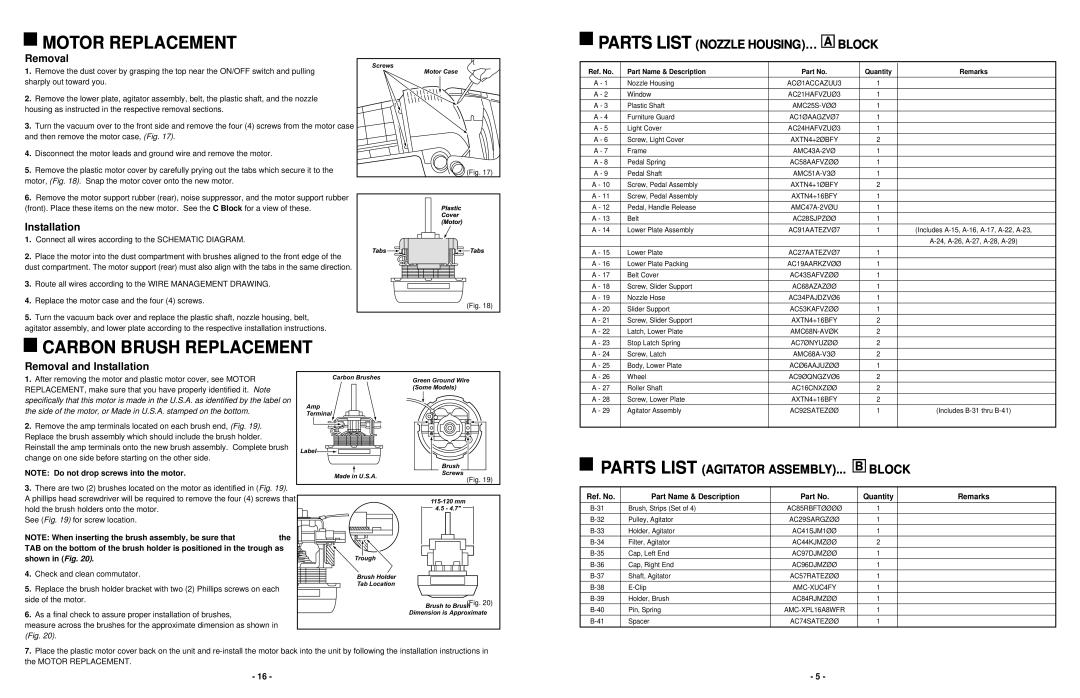
CARBON BRUSH REPLACEMENT
MOTOR REPLACEMENT
PARTS LIST NOZZLE HOUSING… A BLOCK
PARTS LIST AGITATOR ASSEMBLY... B BLOCK
POWER CORD/ON-OFFSWITCH REPLACEMENT Cont
HOSE REPLACEMENT
Replacement
Installation
POWER CORD/ON-OFFSWITCH REPLACEMENT
SWITCH COVER AREA WIRING MANAGEMENT
DUST COMPARTMENT COMPONENT LOCATIONS
Removal
PARTS LIST MOTOR FAN ASSEMBLY
NOZZLE HOUSING AND SHORT HOSE REPLACEMENT
EXPLODED VIEW MOTOR FAN ASSEMBLY
Installation
PARTS LIST PACKAGING
BRUSH REPLACEMENT
When to replace brushes
AGITATOR ASSEMBLY
AGITATOR ASSEMBLY REMOVAL/INSTALLATION
LOWER PLATE REMOVAL/INSTALLATION
BELT REPLACEMENT
Installation
Top
Page
Image
Contents