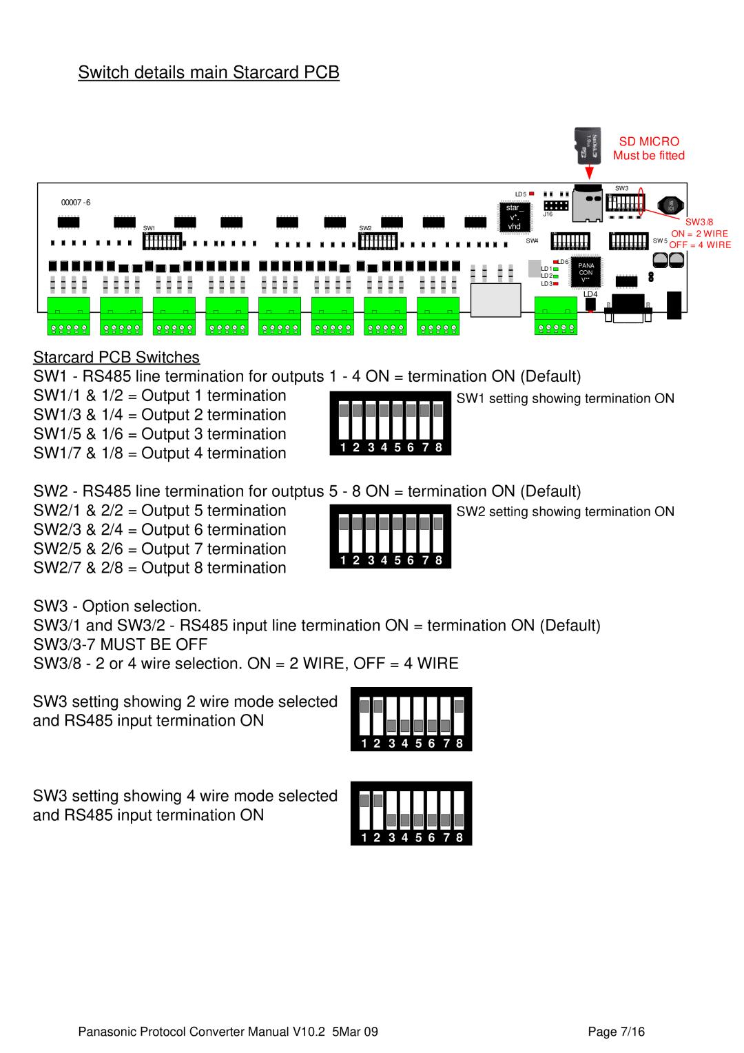
Switch details main Starcard PCB
SD MICRO
Must be fitted
00007
SW1
ON
1 | 2 | 3 | 4 | 5 | 6 | 7 | 8 |
LD 5 ![]()
![]()
| star_ | J16 |
| v*. | |
SW2 | vhd |
|
ON |
|
|
|
|
|
|
| ON |
|
|
|
|
|
|
|
|
|
|
|
|
|
|
| SW4 |
|
|
|
|
|
|
|
1 | 2 | 3 | 4 | 5 | 6 | 7 | 8 | 1 | 2 | 3 | 4 | 5 | 6 | 7 | 8 |
SW3
ON
1 2 3 4 5 6 7 8
ON
1 2 3 4 5 6 7 8
SW3/8
ON = 2 WIRE SW 5 OFF = 4 WIRE
LD1 | LD6 | PANA |
| ||
| CON | |
LD2 |
| |
| V** | |
LD3 |
| |
|
|
LD4 |
Starcard PCB Switches
SW1 - RS485 line termination for outputs 1 - 4 ON = termination ON (Default) SW1/1 & 1/2 = Output 1 termination
SW1/3 & 1/4 = Output 2 termination SW1/5 & 1/6 = Output 3 termination
SW1/7 & 1/8 = Output 4 termination
SW2 - RS485 line termination for outptus 5 - 8 ON = termination ON (Default) SW2/1 & 2/2 = Output 5 termination
SW2/3 & 2/4 = Output 6 termination SW2/5 & 2/6 = Output 7 termination
SW2/7 & 2/8 = Output 8 termination
SW3 - Option selection.
SW3/1 and SW3/2 - RS485 input line termination ON = termination ON (Default)
SW3/8 - 2 or 4 wire selection. ON = 2 WIRE, OFF = 4 WIRE
SW3 setting showing 2 wire mode selected and RS485 input termination ON
1 2 3 4 5 6 7 8
SW3 setting showing 4 wire mode selected and RS485 input termination ON
1 2 3 4 5 6 7 8
Panasonic Protocol Converter Manual V10.2 5Mar 09 | Page 7/16 |