Connections
HDMI connection
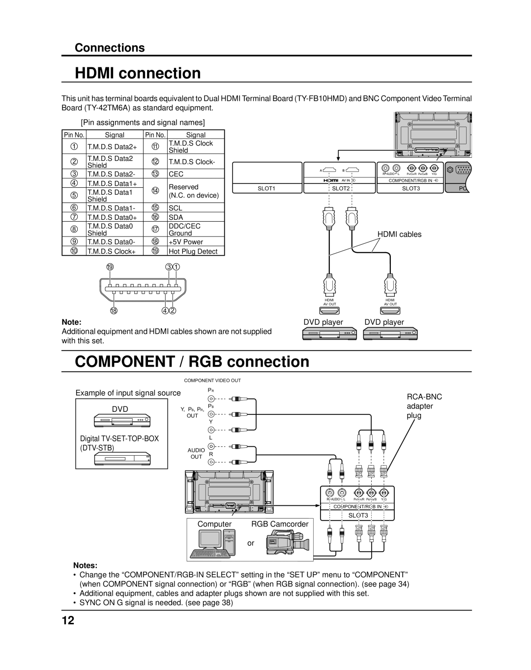
This unit has terminal boards equivalent to Dual HDMI Terminal Board
[Pin assignments and signal names]
Pin No. | Signal | Pin No. |
| Signal |
|
1 | T.M.D.S Data2+ | 11 | T.M.D.S Clock |
| |
Shield |
| ||||
| T.M.D.S Data2 |
|
| ||
2 | 12 | T.M.D.S Clock- |
| ||
Shield |
| ||||
3 | 13 |
|
|
| |
T.M.D.S Data2- | CEC |
| |||
4 | T.M.D.S Data1+ | 14 | Reserved | SLOT1 | |
| T.M.D.S Data1 | ||||
5 | (N.C. on device) |
| |||
Shield |
|
| |||
6 | 15 |
|
|
| |
T.M.D.S Data1- | SCL |
| |||
7 | T.M.D.S Data0+ | 16 | SDA |
| |
8 | T.M.D.S Data0 | 17 | DDC/CEC |
| |
Shield | Ground |
| |||
9 | 18 |
| |||
T.M.D.S Data0- | +5V Power |
| |||
10 | T.M.D.S Clock+ | 19 | Hot Plug Detect |
| |
| 19 |
| 3 | 1 |
|
18 | 4 | 2 |
Note:
Additional equipment and HDMI cables shown are not supplied with this set.
R AUDIO L | PR/CR/R PB/CB/B | Y/G |
COMPONENT/RGB IN | ||
SLOT2 | SLOT3 | PC |
HDMI cables
HDMI | HDMI |
AV OUT | AV OUT |
DVD player |
| DVD player | ||||||||||||
|
|
|
|
|
|
|
|
|
|
|
|
|
|
|
|
|
|
|
|
|
|
|
|
|
|
|
|
|
|
|
|
|
|
|
|
|
|
|
|
|
|
|
|
|
|
|
|
|
|
|
|
|
|
|
|
|
|
|
|
COMPONENT / RGB connection
| COMPONENT VIDEO OUT |
| |
Example of input signal source | PR |
| |
| |||
|
|
| |
DVD | Y, PB, PR, | PB | adapter |
| plug | ||
| OUT | Y | |
|
|
| |
Digital |
| L |
|
| AUDIO | R |
|
| OUT |
| |
R![]() AUDIO
AUDIO![]() L PR/CR/R PB/CB/B Y/G
L PR/CR/R PB/CB/B Y/G
COMPONENT/RGB IN ![]()
SLOT3
Computer | RGB Camcorder |
or
Notes:
•Change the
•Additional equipment, cables and adapter plugs shown are not supplied with this set.
•SYNC ON G signal is needed. (see page 38)
12