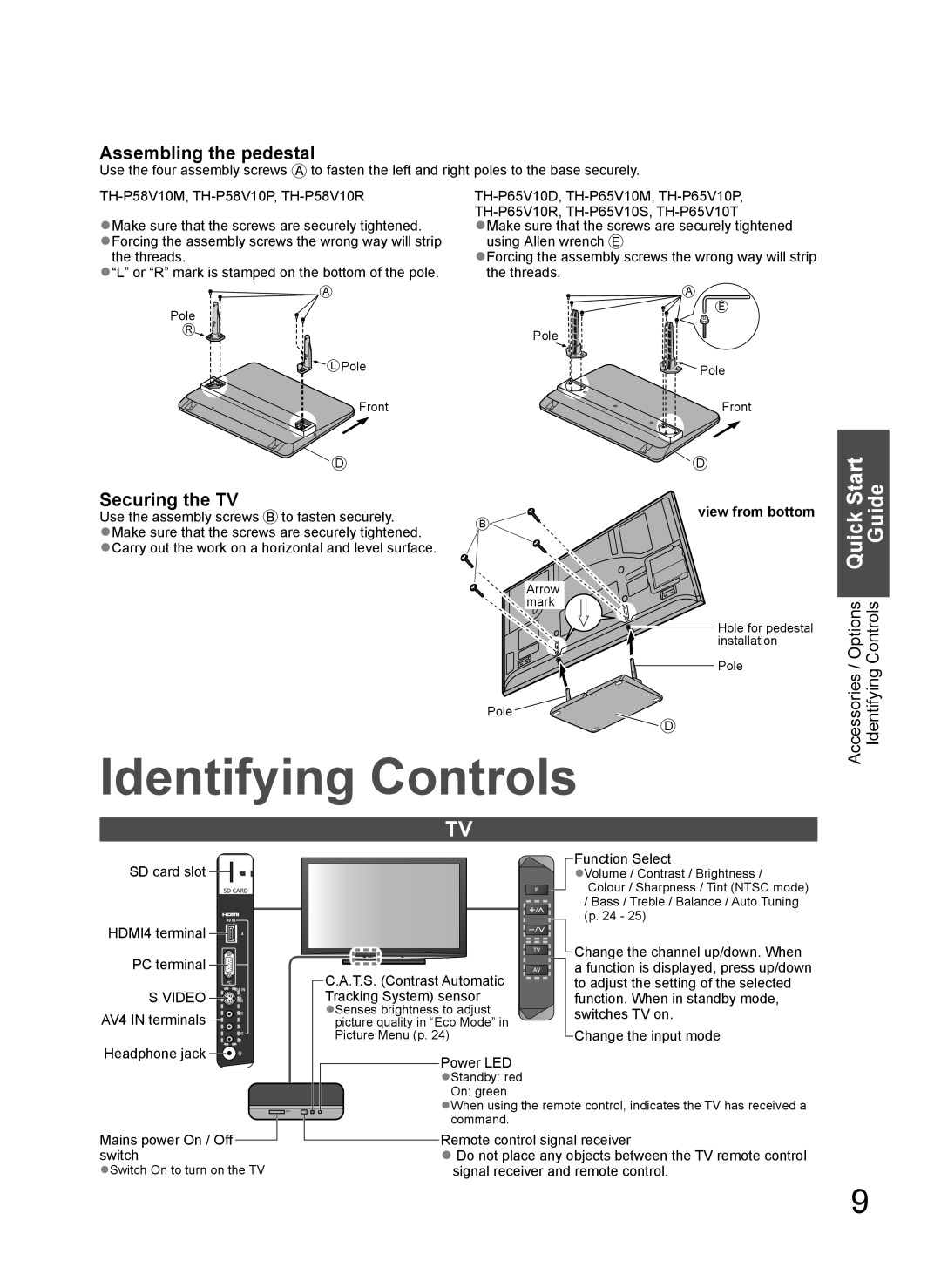
Assembling the pedestal
Use the four assembly screws ![]() to fasten the left and right poles to the base securely.
to fasten the left and right poles to the base securely.
●Make sure that the screws are securely tightened. ●Forcing the assembly screws the wrong way will strip
the threads.
●“L” or “R” mark is stamped on the bottom of the pole.
A
Pole
R
![]() L Pole
L Pole
using Allen wrench E
●Forcing the assembly screws the wrong way will strip the threads.
A
E
Pole
![]() Pole
Pole
Front | Front |
D | D |
Start |
Securing the TV
Use the assembly screws  to fasten securely.
●Make sure that the screws are securely tightened. ●Carry out the work on a horizontal and level surface.
B
Arrow mark
Pole ![]()
view from bottom
Hole for pedestal installation
Pole
![]() D
D
Quick Guide |
Accessories / Options Identifying Controls |
Identifying Controls
TV
SD card slot ![]()
![]()
![]()
HDMI4 terminal ![]()
![]() PC terminal
PC terminal ![]()
![]()
SVIDEO ![]()
![]()
![]()
![]() AV4 IN terminals
AV4 IN terminals ![]()
![]()
![]()
C.A.T.S. (Contrast Automatic Tracking System) sensor ●Senses brightness to adjust
picture quality in “Eco Mode” in Picture Menu (p. 24)
Function Select
●Volume / Contrast / Brightness / Colour / Sharpness / Tint (NTSC mode) / Bass / Treble / Balance / Auto Tuning (p. 24 - 25)
Change the channel up/down. When a function is displayed, press up/down to adjust the setting of the selected function. When in standby mode, switches TV on.
Change the input mode
Headphone jack ![]()
![]()
![]()
Mains power On / Off ![]() switch
switch
●Switch On to turn on the TV
Power LED ●Standby: red On: green
●When using the remote control, indicates the TV has received a command.
Remote control signal receiver
●Do not place any objects between the TV remote control signal receiver and remote control.
9