Introduction and Installation
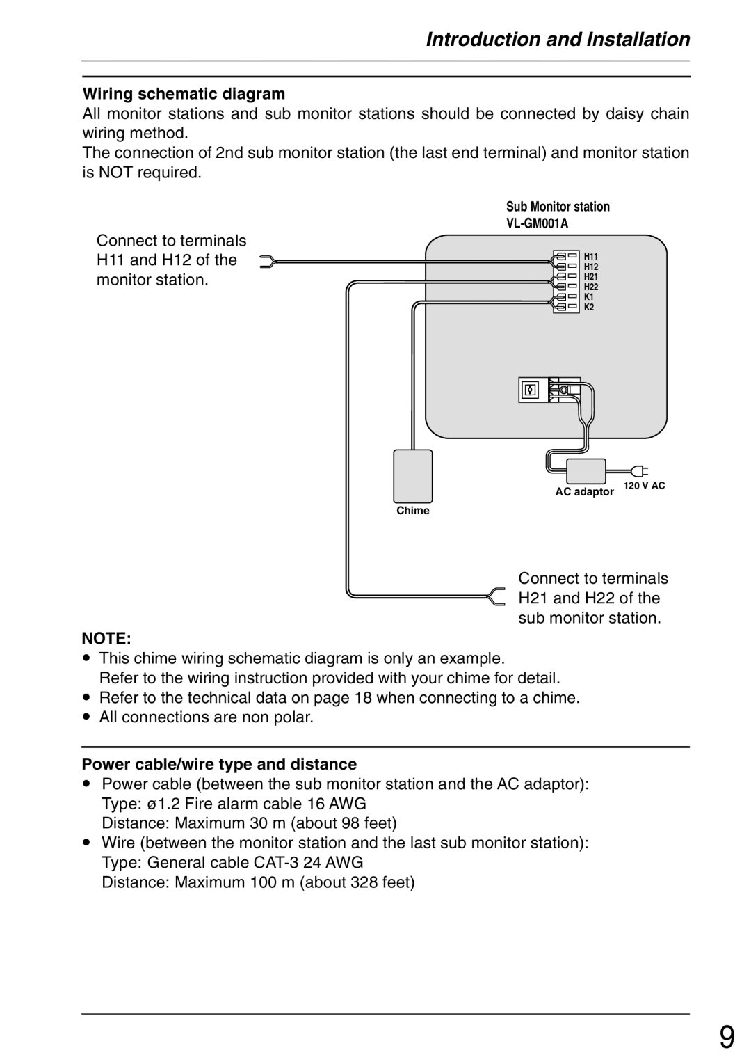
Wiring schematic diagram
All monitor stations and sub monitor stations should be connected by daisy chain wiring method.
The connection of 2nd sub monitor station (the last end terminal) and monitor station is NOT required.
Connect to terminals H11 and H12 of the monitor station.
Sub Monitor station
H11
H12
H21
H22
K1
K2
AC adaptor
Chime
120 V AC
Connect to terminals H21 and H22 of the sub monitor station.
NOTE:
•This chime wiring schematic diagram is only an example.
Refer to the wiring instruction provided with your chime for detail.
•Refer to the technical data on page 18 when connecting to a chime.
•All connections are non polar.
Power cable/wire type and distance
•Power cable (between the sub monitor station and the AC adaptor): Type: ø1.2 Fire alarm cable 16 AWG
Distance: Maximum 30 m (about 98 feet)
•Wire (between the monitor station and the last sub monitor station): Type: General cable
Distance: Maximum 100 m (about 328 feet)
9
