Cautions:
1.CONNECT THIS TO 24 V AC CLASS 2 POWER SUPPLY ONLY. Be sure to connect the grounding lead to the GND terminal.
2.To prevent fire or electric shock hazard, use a UL listed cable
3.The connections should comply with National Electrical Code (NEC).
CONNECTIONS
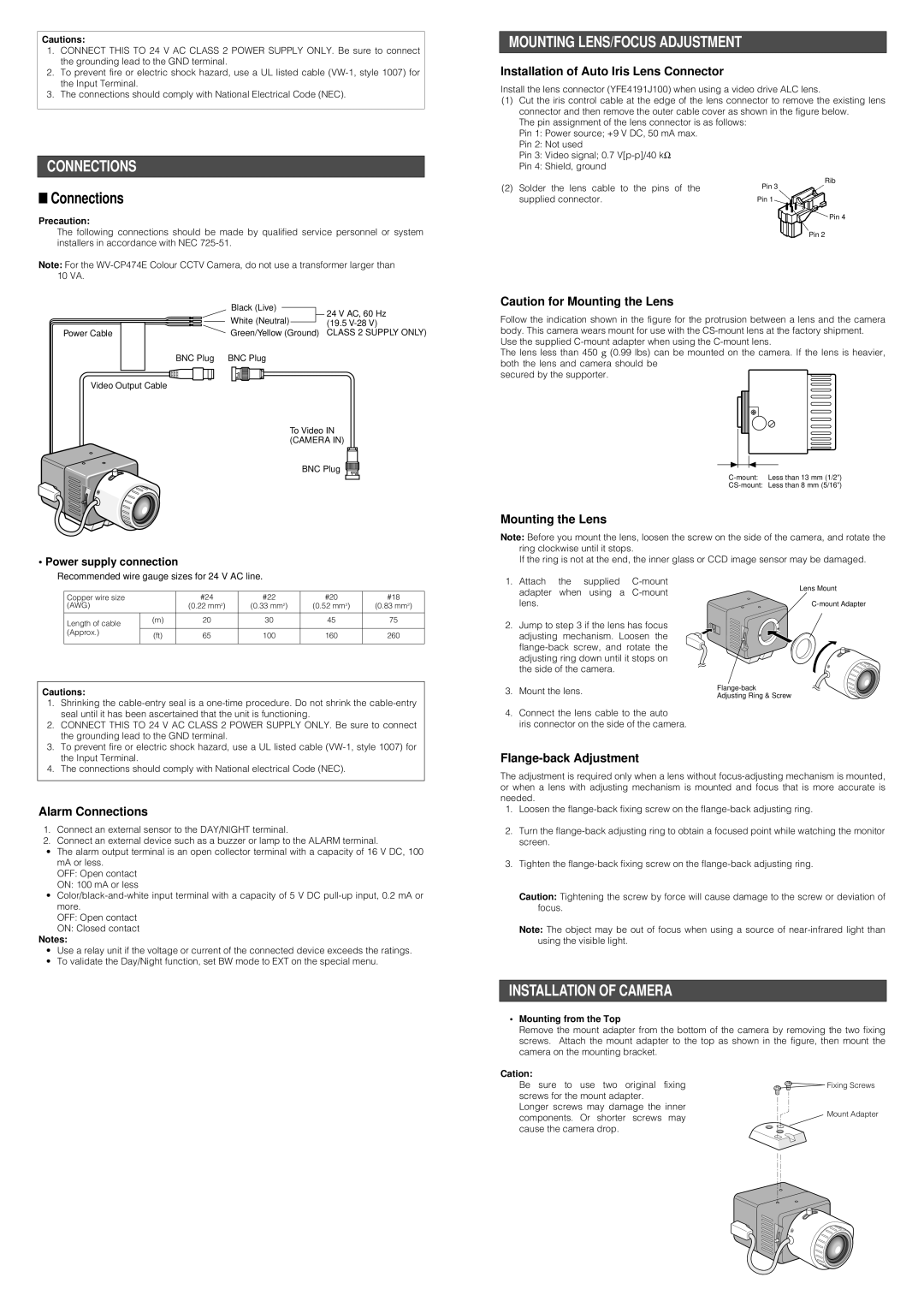
■Connections
Precaution:
The following connections should be made by qualified service personnel or system installers in accordance with NEC
Note: For the
| Black (Live) | 24 V AC, 60 Hz |
| White (Neutral) | |
| (19.5 | |
Power Cable | Green/Yellow (Ground) | CLASS 2 SUPPLY ONLY) |
BNC Plug | BNC Plug |
|
Video Output Cable |
|
|
To Video IN (CAMERA IN)
BNC Plug
• Power supply connection
MOUNTING LENS/FOCUS ADJUSTMENT
Installation of Auto Iris Lens Connector
Install the lens connector (YFE4191J100) when using a video drive ALC lens.
(1)Cut the iris control cable at the edge of the lens connector to remove the existing lens connector and then remove the outer cable cover as shown in the figure below.
The pin assignment of the lens connector is as follows: Pin 1: Power source; +9 V DC, 50 mA max.
Pin 2: Not used
Pin 3: Video signal; 0.7
Pin 4: Shield, ground
Rib
(2) Solder the lens cable to the pins of the | Pin 3 |
supplied connector. | Pin 1 |
Pin 4
Pin 2
Caution for Mounting the Lens
Follow the indication shown in the figure for the protrusion between a lens and the camera body. This camera wears mount for use with the
Use the supplied
The lens less than 450 g (0.99 lbs) can be mounted on the camera. If the lens is heavier, both the lens and camera should be
secured by the supporter.
Mounting the Lens
Note: Before you mount the lens, loosen the screw on the side of the camera, and rotate the ring clockwise until it stops.
If the ring is not at the end, the inner glass or CCD image sensor may be damaged.
Recommended wire gauge sizes for 24 V AC line.
Copper wire size |
| #24 | #22 | #20 | #18 |
(AWG) |
| (0.22 mm2) | (0.33 mm2) | (0.52 mm2) | (0.83 mm2) |
|
|
|
|
|
|
Length of cable | (m) | 20 | 30 | 45 | 75 |
|
|
|
|
| |
(Approx.) | (ft) | 65 | 100 | 160 | 260 |
| |||||
|
|
|
|
|
|
Cautions:
1.Attach the supplied
2.Jump to step 3 if the lens has focus adjusting mechanism. Loosen the
3.Mount the lens.
Lens Mount
Adjusting Ring & Screw
1.Shrinking the
2.CONNECT THIS TO 24 V AC CLASS 2 POWER SUPPLY ONLY. Be sure to connect the grounding lead to the GND terminal.
3.To prevent fire or electric shock hazard, use a UL listed cable
4.The connections should comply with National electrical Code (NEC).
Alarm Connections
1.Connect an external sensor to the DAY/NIGHT terminal.
2.Connect an external device such as a buzzer or lamp to the ALARM terminal.
•The alarm output terminal is an open collector terminal with a capacity of 16 V DC, 100 mA or less.
OFF: Open contact
ON: 100 mA or less
•
more.
OFF: Open contact
ON: Closed contact
Notes:
•Use a relay unit if the voltage or current of the connected device exceeds the ratings.
•To validate the Day/Night function, set BW mode to EXT on the special menu.
4.Connect the lens cable to the auto
iris connector on the side of the camera.
Flange-back Adjustment
The adjustment is required only when a lens without
1.Loosen the
2.Turn the
3.Tighten the
Caution: Tightening the screw by force will cause damage to the screw or deviation of focus.
Note: The object may be out of focus when using a source of
INSTALLATION OF CAMERA
•Mounting from the Top
Remove the mount adapter from the bottom of the camera by removing the two fixing screws. Attach the mount adapter to the top as shown in the figure, then mount the camera on the mounting bracket.
Cation: |
| |
Be sure to use two original fixing | Fixing Screws | |
screws for the mount adapter. |
| |
Longer screws may damage the inner | Mount Adapter | |
components. Or shorter screws may | ||
| ||
cause the camera drop. |
|