r
30 3/8 X
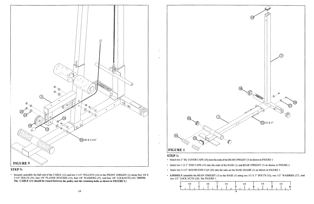
FIGURE 9
STEP 9:
•Securely assemble the ball end of the CABLE (12) and two
The CABLE (12) should be routed between the pulley and the retaining bolts as shown in FIGURE 9.)
FIGURE 1
STEP 1:
•Attach two 2" SQ. COVER CAPS (18) onto the ends ofthe REAR UPRIGHT (3) as shown in FIGURE 1.
•Insert two 3 X 2" END CAPS (19) into the ends of the BASE (1) and REAR UPRIGHT (3) as shown in FIGURE 1.
•Insert two
•LOOSELY assemble the REAR UPRIGHT (3) to the BASE (1) using two 1/2 X 3" BOLTS (32), two 1/2" WASHERS (27), and two 1/2" LOCK NUTS (28). See FIGURE 1.
|
|
|
|
|
|
|
|
|
|
|
|
|
|
|
|
|
| [ |
| I | 1/2 | I | 1/2 | I | 1/2 |
| I | 1/2 | I | 1/2 |
| I | 1/2 |
| |||
I | I | 1 | I | 2 | I |
| I | I | I | I |
| I | I | I | ||||
o |
|
|
| 3 |
| 4 |
| 5 |
| 6 | ||||||||
13 | 6 |