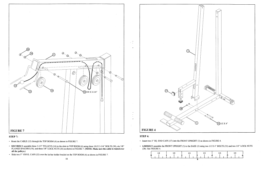
FIGURE 7
STEP 7:
•Route the CABLE (12) through the TOP BOOM (4) as shown in FIGURE 7.
•SECURELY assemble three
•Slide two 5" VINYL CAPS (22) over the lat bar holder bracket on the TOP BOOM (4) as shown in FIGURE 7.
I
FIGURE 4
STEP 4:
•Insert two 2" SQ. END CAPS (17) into the FRONT UPRIGHT (3) as shown in FIGURE 4.
•LOOSELY assemble the FRONT UPRIGHT (3) to the BASE (1) using two 112 X 4" BOLTS (32) and two 112" LOCK NUTS (28). See FIGURE 4.
|
|
|
|
|
|
|
|
|
|
|
|
|
|
|
| I | |
I | 1/2 | I | 1/2 | I | 1/2 |
| I | 1/2 | I | I | 1/2 |
| |||||
o | I | 1 | I | 2 | I | 3 | I | 4 | 5 | I | 6 |
| |||||
| I | I | I |
| I | I | I | I |
| ||||||||
11 | 8 |
