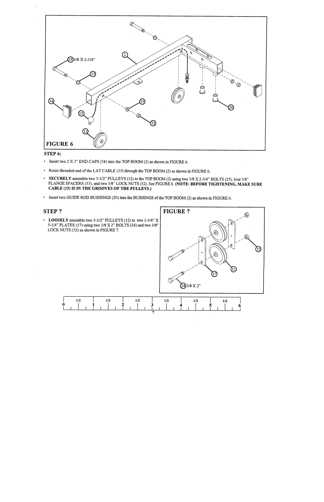
I FIGURE6

STEP 6:

¯Insert two 2 X 3" ENDCAPS(34) into the TOPBOOM(2) as shown in FIGURE

Route threaded end of the LATCABLE(15) through the TOPBOOM(2) as shown in FIGURE

SECURELYassemble two 3-1/2" PULLEYS(12) to the TOPBOOM(2) using two 3/8 X 2-3/4" BOLTS(25), four FLANGESPACERS(33), and two 3/8" LOCKNUTS(32). See FIGURE 6. (NOTE: BEFORETIGIITENING, MAKE

CABLE(15) IS IN TIlE GROOVESOF TIlE PULLEYS.)

¯Insert two GUIDERODBUSHINGS(20) into the BUSHINGSof the TOPBOOM(2) as shown in FIGURE

STEP 7FIGURE 7

LOOSELYassemble two 3-1/2" PULLEYS(12) to two 1-3/4" 5-1/4" PLATES(17) using two 3/8 X 2" BOLTS(24) and 3/8" LOCKNUTS(32) as shown in FIGURE

~3/8 X 2"

1/21/2

0123

Page 7
Image 7
ParaBody 841101 manual CABLE15 is in TIlE Groovesof TIlE Pulleys