9
20
1
32
26 3/8 X 4-1/2”
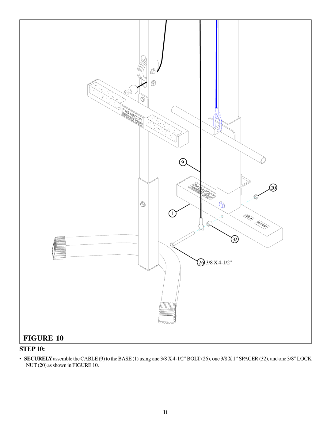
FIGURE 10
•SECURELY assemble the CABLE (9) to the BASE (1) using one 3/8 X 4-1/2” BOLT (26), one 3/8 X 1” SPACER (32), and one 3/8” LOCK NUT (20) as shown in FIGURE 10.
11