18 |
2 |
40 |
42 |
30 3/8 X |
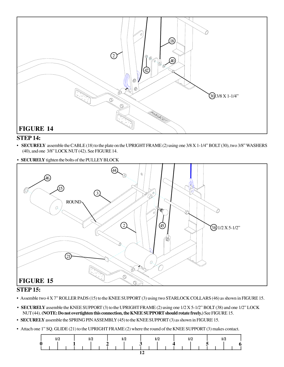
FIGURE 14 |
STEP 14:
•SECURELY assemble the CABLE (18) to the plate on the UPRIGHT FRAME (2) using one 3/8 X
•SECURELY tighten the bolts of the PULLEY BLOCK
44
46
15
3
ROUND
2 | 45 | 38 1/2 X |
|
|
21 ![]()
FIGURE 15
STEP 15:
•Assemble two 4 X 7” ROLLER PADS (15) to the KNEE SUPPORT (3) using two STARLOCK COLLARS (46) as shown in FIGURE 15.
•SECURELY assemble the KNEE SUPPORT (3) to the UPRIGHT FRAME (2) using one 1/2 X
•SECURELY assemble the SPRING PINASSEMBLY (45) to the KNEE SUPPORT (3) as shown in FIGURE 15.
•Attach one 1” SQ. GLIDE (21) to the UPRIGHT FRAME (2) where the round of the KNEE SUPPORT (3) makes contact.
| 1/2 |
| 1/2 |
| 1/2 |
| 1/2 |
| 1/2 |
|
| 1/2 |
0 | 1 | 2 | 3 | 4 | 5 | 6 | ||||||
12
