|
| 7 |
|
| 44 |
|
| 2 |
| 5 |
|
|
| 43 |
|
| 35 1/2 X 3” |
|
| 14 |
| 44 | 43 |
|
| |
FIGURE 5 |
| 1/2 X 3” 35 |
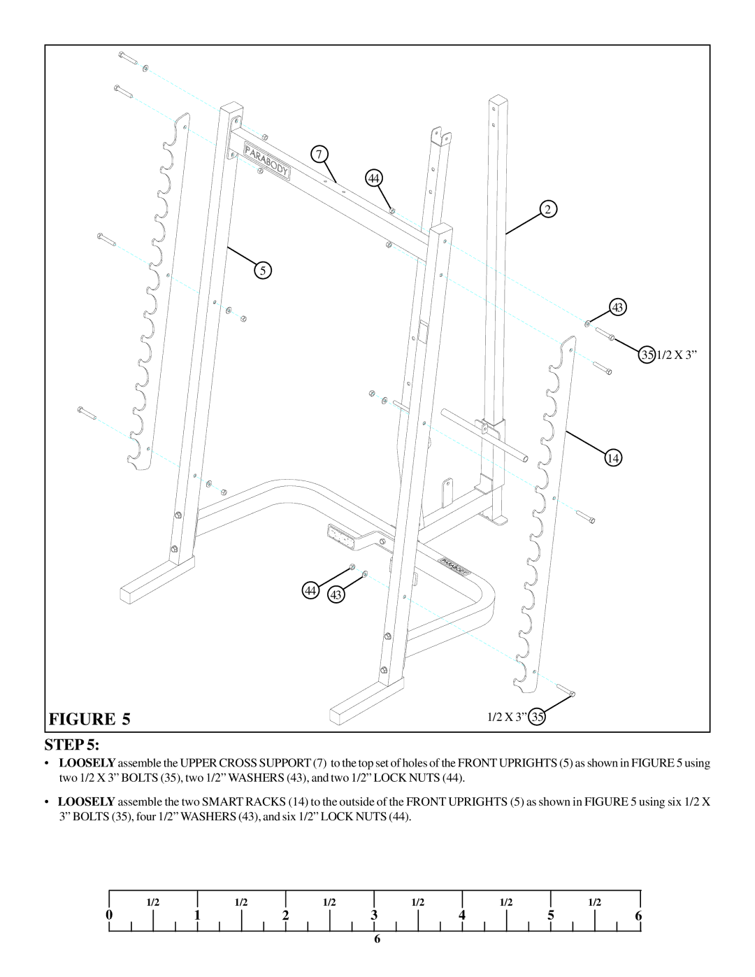
STEP 5:
•LOOSELY assemble the UPPER CROSS SUPPORT (7) to the top set of holes of the FRONT UPRIGHTS (5) as shown in FIGURE 5 using two 1/2 X 3” BOLTS (35), two 1/2” WASHERS (43), and two 1/2” LOCK NUTS (44).
•LOOSELY assemble the two SMART RACKS (14) to the outside of the FRONT UPRIGHTS (5) as shown in FIGURE 5 using six 1/2 X 3” BOLTS (35), four 1/2” WASHERS (43), and six 1/2” LOCK NUTS (44).
| 1/2 |
| 1/2 |
| 1/2 |
| 1/2 |
| 1/2 |
|
| 1/2 |
0 | 1 | 2 | 3 | 4 | 5 | 6 | ||||||
6