FIGURE 8 |
|
| 1/2 X |
|
|
| |
5 | 42 | 1 | 44 |
|
|
| |
|
|
| 43 |
| 42 |
|
|
|
|
| 35 1/2 X 3” |
19 | 7 |
| 32 3/8 X |
|
|
| |
|
|
| 2 |
| 40 |
|
|
| 33 3/8 X 4” |
|
|
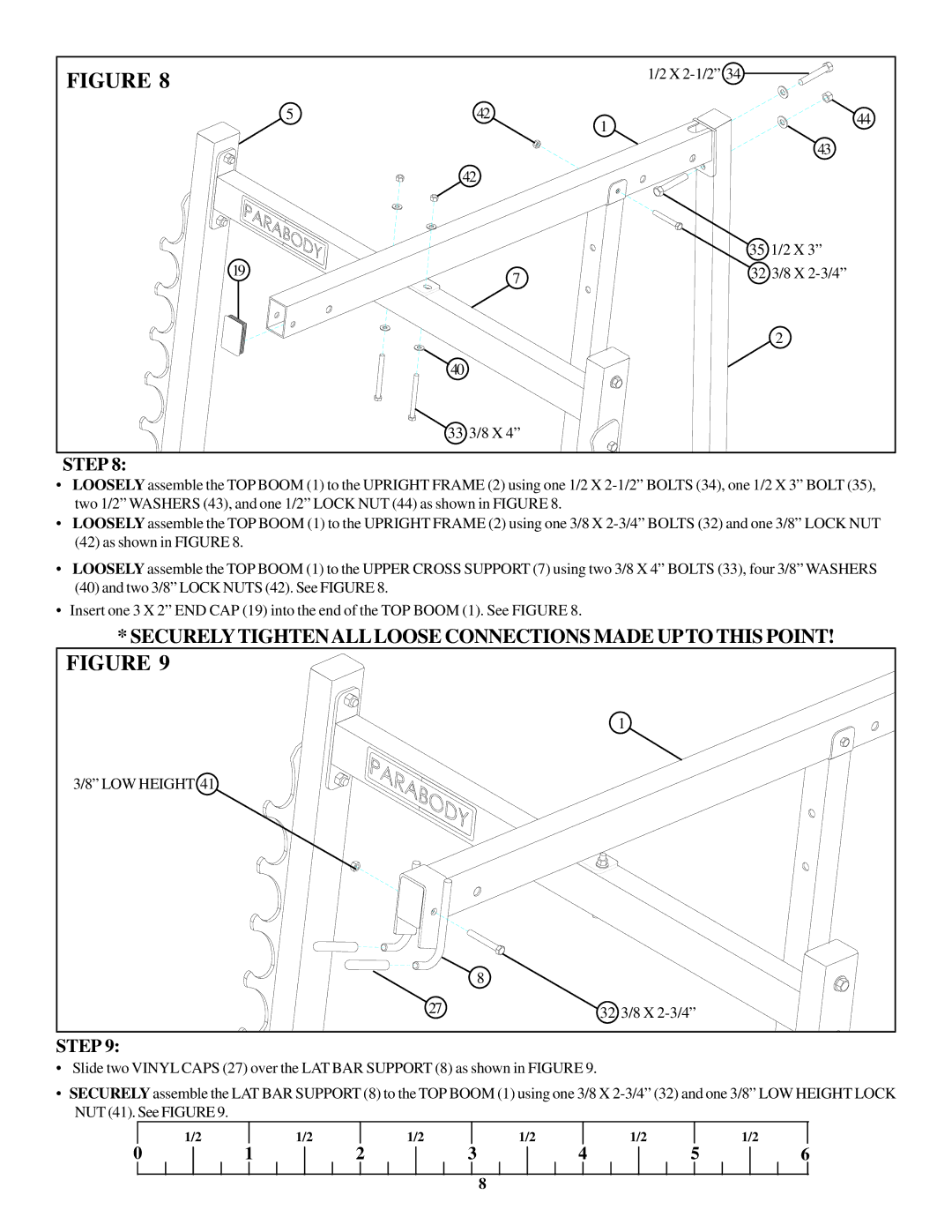
STEP 8:
•LOOSELY assemble the TOP BOOM (1) to the UPRIGHT FRAME (2) using one 1/2 X
•LOOSELY assemble the TOP BOOM (1) to the UPRIGHT FRAME (2) using one 3/8 X
(42)as shown in FIGURE 8.
•LOOSELY assemble the TOP BOOM (1) to the UPPER CROSS SUPPORT (7) using two 3/8 X 4” BOLTS (33), four 3/8” WASHERS
(40)and two 3/8” LOCK NUTS (42). See FIGURE 8.
•Insert one 3 X 2” END CAP (19) into the end of the TOP BOOM (1). See FIGURE 8.
*SECURELYTIGHTENALLLOOSE CONNECTIONS MADE UPTO THIS POINT!
FIGURE 9 |
|
| 1 |
3/8” LOW HEIGHT 41 |
|
| 8 |
27 | 32 3/8 X |
STEP 9:
•Slide two VINYL CAPS (27) over the LAT BAR SUPPORT (8) as shown in FIGURE 9.
•SECURELY assemble the LAT BAR SUPPORT (8) to the TOP BOOM (1) using one 3/8 X
| 1/2 |
| 1/2 |
| 1/2 |
| 1/2 |
| 1/2 |
|
| 1/2 |
0 | 1 | 2 | 3 | 4 | 5 | 6 | ||||||
8