| | | FIGURE 21 |
| | | 55 3/8 X 2-3/4” |
| 63 | | |
| | 7 | 5 |
3/8 X 2-3/4” 55 | | | 56 |
| | |
| | 39 | 63 |
| | |
| 38 | 4-1/2” | |
31 | 50 | | |
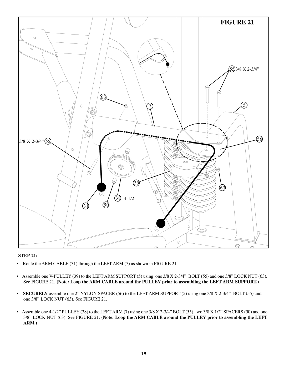
STEP 21: | | | |
•Route the ARM CABLE (31) through the LEFT ARM (7) as shown in FIGURE 21.
•Assemble one V-PULLEY (39) to the LEFT ARM SUPPORT (5) using one 3/8 X 2-3/4” BOLT (55) and one 3/8” LOCK NUT (63). See FIGURE 21. (Note: Loop the ARM CABLE around the PULLEY prior to assembling the LEFT ARM SUPPORT.)
•SECURELY assemble one 2” NYLON SPACER (56) to the LEFT ARM SUPPORT (5) using one 3/8 X 2-3/4” BOLT (55) and one 3/8” LOCK NUT (63). See FIGURE 21.
•Assemble one 4-1/2” PULLEY (38) to the LEFT ARM (7) using one 3/8 X 2-3/4” BOLT (55), two 3/8 X 1/2” SPACERS (50) and one 3/8” LOCK NUT (63). See FIGURE 21. (Note: Loop the ARM CABLE around the PULLEY prior to assembling the LEFT
ARM.)