3 |
43 |
2 |
40 |
FIGURE 9 |
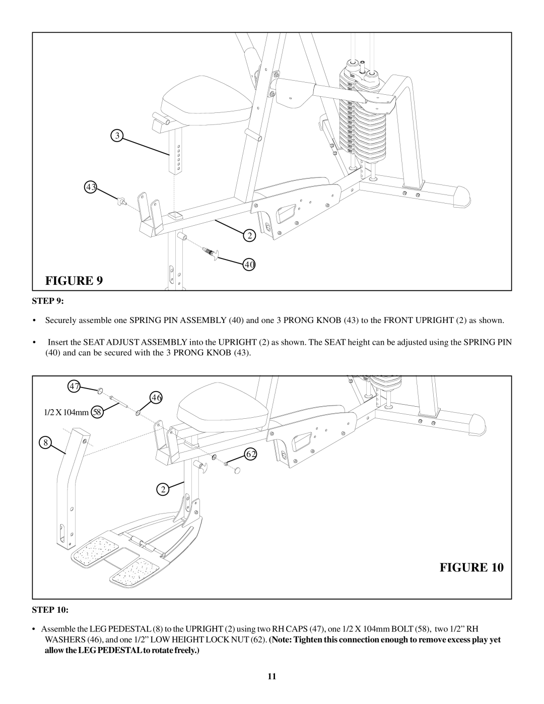
STEP 9:
•Securely assemble one SPRING PIN ASSEMBLY (40) and one 3 PRONG KNOB (43) to the FRONT UPRIGHT (2) as shown.
•Insert the SEAT ADJUST ASSEMBLY into the UPRIGHT (2) as shown. The SEAT height can be adjusted using the SPRING PIN
(40)and can be secured with the 3 PRONG KNOB (43).
47 |
46 |
1/2 X 104mm 58 |
8 |
62 |
2 |
FIGURE 10 |
STEP 10:
•Assemble the LEG PEDESTAL (8) to the UPRIGHT (2) using two RH CAPS (47), one 1/2 X 104mm BOLT (58), two 1/2” RH WASHERS (46), and one 1/2” LOW HEIGHT LOCK NUT (62). (Note: Tighten this connection enough to remove excess play yet allow the LEGPEDESTALto rotate freely.)
11