Manuals
/
Paradyne
/
Computer Equipment
/
Modem
Paradyne
4300 Figure K - Fan/Filter Replacement Diagram, Filter Maintenance
Models:
4300
1
19
22
22
Download
22 pages
44.05 Kb
15
16
17
18
19
20
21
22
Specs
Install
Figure H - Grounding Diagram
Ground Wire
Maintenance
Cabinet Configurations
Connector DSL
Line Power
Using This Installation Guide
Page 19
Image 19
Page 18
Page 20
Page 19
Image 19
Page 18
Page 20
Contents
Document Number 4300-A2-GZ40-00
Contents
Installation Instructions
4300 Remote Broadband Access Concentrator
Product Documentation Online
Using This Installation Guide
Trademarks
Warranty, Sales, Service, and Training Information
Inspecting Shipment
Product Overview
Connect Panels Swing out racks for Protection/Cross Connect Panels
Figure A - Front view of cabinet with door open
Rectifier or DC-DC Converter
Cabinet lifting eyelets GranDSLAM DSLAMs Protection/Cross
Figure B - Front view of cabinet without equipment
CABINET CONFIGURATIONS
Table 1 - Expansion, Mounting and Maintenance Kits
EXPANSION, MOUNTING AND MAINTENANCE KITS
Figure C - Cabinet overall dimensions
PRODUCT SPECIFICATIONS
Figure D - Quarter turn locking door latches
QUARTER-TURN LOCKING DOOR LATCHES
Lifting eyelets are provided to facilitate hoisting if desired
Installation Procedure
CLEARANCE REQUIREMENTS
Figure E - Cabinet Footprint
Figure F - Pole Mounting Diagram
INSTALLATION PROCEDURE FOR POLE MOUNTING
Have the following equipment ready before beginning this procedure
Figure G - Wall Mounting Diagram
INSTALLATION PROCEDURE FOR WALL MOUNTING
Lifting eyelets are provided to facilitate hoisting if desired
Cabinet Grounding Information
GROUND WIRE
Figure H - Grounding Diagram
GROUNDING DIAGRAM AND PROCEDURE
unterminated
Protection/Cross Connects
Figure I - Protection/Cross Connect Panel, top view 50 pair
Figure J -Cross Connect Panel, front view
Connector POTS
Protection/Cross Connect Wiring Tables
Table 2 - Protection Cross Connect Cable Wiring
Connector DSL
WHITE / BROWN
Table 3 - Cross Connect Panel Wiring
WHITE / ORANGE
WHITE / BLUE
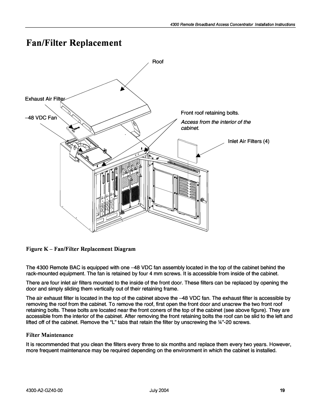
Figure K - Fan/Filter Replacement Diagram
Fan/Filter Replacement
Filter Maintenance
Figure L - Model 1 Schematic Wiring Diagram
EXTERNAL WIRING
LINE POWER
SCHEMATIC WIRING DIAGRAMS
Figure M - Model 2 Schematic Wiring Diagram
4300-A2-GZ40-00
Figure N - Model 3 Schematic Wiring Diagram
Top
Page
Image
Contents