LED Symptom
Action
DSL and Ethernet | The DSL link and the Ethernet link have been established but |
LEDs are on and | there is no data transmission. If the problem continues, contact |
there is no data | the NSP. |
transmission. |
|
|
|
Ethernet LED is off. | Verify that the Ethernet 10BaseT cable is securely installed at |
| both ends, and at least one PC is connected and powered on. |
|
|
| Verify that the correct |
| installed. Refer to Installing the Hotwire 5620 RTU, page 8. |
|
|
PWR LED is off. | Check that the power cord is securely installed on both ends. |
|
|
| If no LEDs are on, the power supply may be defective. Test the |
| outlet to verify power. If the problem persists, contact the NSP. |
|
|
| If other LEDs are on, the PWR LED may be burned out. Unplug |
| the unit and reapply power; watch all LEDs during the |
| |
|
|
TST LED is on. | A test initiated by the NSP may be active. Wait five minutes. |
| If the TST LED does not go off, contact the NSP. |
|
|
Increasing the Number of End-User Systems
A single PC is attached to the Hotwire 5620 RTU using an Ethernet crossover cable. To increase the number of PCs, connect all PCs to an Ethernet hub using a
The Hotwire 5620 RTU can support up to 32 PCs. Verify any changes with the NSP.
Cables & Connectors
Use standard
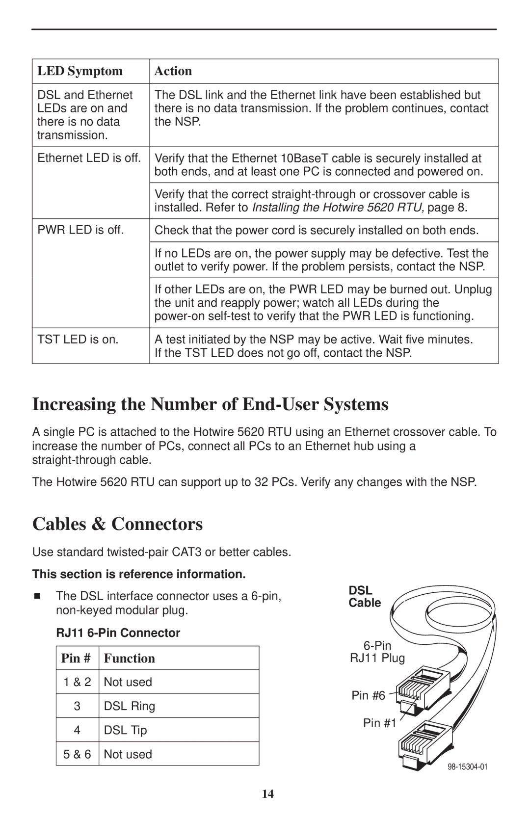
This section is reference information.
HThe DSL interface connector uses a
RJ11
Pin # Function
1 & 2 Not used
3DSL Ring
4DSL Tip 5 & 6 Not used
DSL
Cable
RJ11 Plug
Pin #6
Pin #1
14