Connecting the DSL Cards to the Ethernet Hubs or Switches
"Procedure
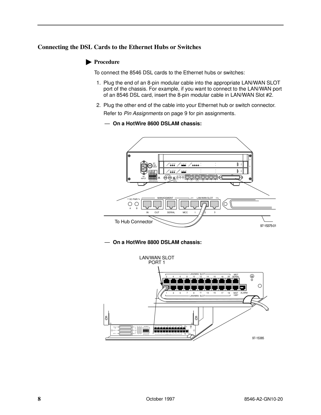
To connect the 8546 DSL cards to the Ethernet hubs or switches:
1.Plug the end of an
2.Plug the other end of the cable into your Ethernet hub or switch connector. Refer to Pin Assignments on page 9 for pin assignments.
ÐOn a HotWire 8600 DSLAM chassis:
| AC |
| T5A |
| 250A |
48V | RTN |
A B | A B |
AC |
|
INPUT |
|
48VDC CLASS 2 OR | |
LIMITED PWR SOURCE | |
SYSTEM | OK | Alrm | Test | ETHERNET | TX | RX | Col | DSL | PORT 1 | 2 | 3 | 4 |
SYSTEM | OK | Alrm | Test | ETHERNET | TX | RX | Col |
|
|
|
|
|
DC FUSES | FAN | DC PWR | MANAGEMENT |
|
| LAN/WAN SLOT | LINE | |||
T4A, MIN. 48V |
|
|
|
|
|
| ||||
| 3 4 | 5 6 . |
|
|
|
|
|
|
|
|
A | 21 | . .. ALM | A | B |
|
|
|
|
|
|
B | STACK |
| IN | OUT | SERIAL | MCC | 1 | 2 | 3 | |
| POSITION |
|
|
|
|
|
|
|
| |
| RADSL | 8546 |
| MCC | 8000 |
| ||
|
|
|
3
2
1
DC PWR | MANAGEMENT |
|
| LAN/WAN SLOT |
| ||
|
|
|
|
|
| ||
A | B |
|
|
|
|
|
|
| IN | OUT | SERIAL | MCC | 1 | 2 | 3 |
To Hub Connector
ÐOn a HotWire 8800 DSLAM chassis:
LAN/WAN SLOT
PORT 1
|
|
|
|
|
|
|
|
|
|
|
|
|
| LAN/WAN SLOT |
|
|
|
|
|
|
|
|
|
|
|
|
| MGT |
|
|
| |||||||||||||||||
|
|
|
|
|
|
|
|
|
|
|
|
|
|
|
| 16 |
|
|
|
|
|
| ||||||||||||||||||||||||||
2 |
| 4 |
| 6 |
| 8 | 10 |
| 12 |
| 14 |
|
| 18 |
| 20 |
| SERIAL |
|
|
|
| ||||||||||||||||||||||||||
|
|
|
|
|
|
|
|
|
|
|
|
|
|
|
|
|
|
|
|
|
|
|
|
|
|
|
|
|
|
|
|
|
|
|
|
|
|
|
|
|
|
|
|
|
|
|
|
|
|
|
|
|
|
|
|
|
|
|
|
|
|
|
|
|
|
|
|
|
|
|
|
|
|
|
|
|
|
|
|
|
|
|
|
|
|
|
|
|
|
|
|
|
|
|
|
|
|
|
|
|
|
|
|
|
|
|
|
|
|
|
|
|
|
|
|
|
|
|
|
|
|
|
|
|
|
|
|
|
|
|
|
|
|
|
|
|
|
|
|
|
|
|
|
|
|
|
1 |
| 3 |
| 5 |
| 7 | 9 |
| 11 |
| 13 |
| 15 |
| 17 |
| 19 |
|
| MGT ALARM | ||||||||||||||||||||||||||||
|
|
|
|
|
|
|
|
|
|
|
|
|
| LAN/WAN SLOT |
|
|
|
|
|
|
|
|
|
|
|
|
| 10BT | ||||||||||||||||||||
|
|
|
|
|
|
|
|
|
|
|
|
|
|
|
|
|
|
|
|
|
|
|
|
|
|
|
|
|
|
|
|
|
|
|
|
|
|
|
|
|
| |||||||
|
|
|
|
|
|
|
|
|
|
|
|
|
|
|
|
|
|
|
|
|
|
|
|
|
|
|
|
|
|
|
|
|
|
|
|
|
|
|
|
|
|
|
|
|
|
|
|
|
SLOTS ![]()
![]() SLOTS
SLOTS ![]()
SLOTS 1 - 6 ![]()
LINES
A![]()
![]() B
B![]()
|
|
|
|
|
|
|
|
|
|
RET (A) | RET (B) | FR GND |
|
|
|
|
| LAN/WAN SLOT |
| 16 |
| 20 |
| MGT | |||||
| 2 | 4 | 6 | 8 | 10 | 12 | 14 | 18 |
| SERIAL | ||||||
|
|
|
|
|
|
|
|
|
|
|
|
|
|
|
|
|
|
|
|
|
|
|
|
|
|
|
|
|
|
|
|
|
|
| 1 | 3 | 5 | 7 | 9 | 11 | 13 | 15 | 17 | 19 |
| MGT ALARM | ||||
|
|
|
|
| LAN/WAN SLOT |
|
|
|
|
| 10BT | |||||
8 | October 1997 |